简介
基于Buildroot构建的Linux SDK,适配SpacemiT K系列芯片。包含监管程序接口(OpenSBI)、引导加载程序(U-Boot/UEFI)、Linux 内核、根文件系统(包含各种中间件和库)以及示例等。其目标是为客户提供处理器 Linux 支持,并且可以开发驱动或应用。
系统架构
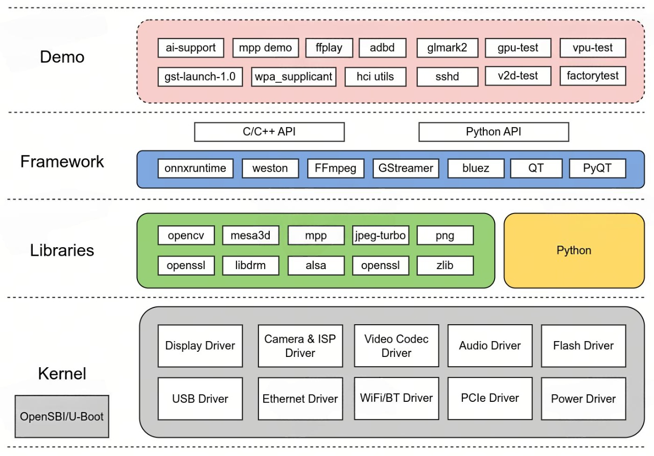
主要组件
SDK包含的组件如下:
- OpenSBI
- U-Boot
- Linux Kernel
- Buildroot
- onnxruntime (with Hardware Accelerated)
- ai-support: AI demo
- img-gpu-powervr: GPU DDK
- mesa3d
- QT 5.15 (with GPU enabled)
- k1x-vpu-firmware: Video Process Unit firmware
- k1x-vpu-test: Video Process Unit test program
- k1x-jpu: JPEG Process Unit API
- k1x-cam: CMOS Sensor and ISP API
- mpp: Media Process Platform
- FFmpeg (with Hardware Accelerated)
- GStreamer (with Hardware Accelerated)
- v2d-test: 2D Unit test program
- factorytest: factory test app
更多组件正在适配中。