Camera Development Guide
This document provides quick start development for the SpacemiT K1 platform's Camera module.
The K1 only supports MIPI type interfaces and uses the SpacemiT camera driver framework.
Camera Quick Bring Up Guide
Bring Up a Supported Camera (Two Steps)
Step 1: Identify the Camera Interface and Run the Command
Identify the MIPI CSI interface that the camera is connected to (for example, CSI1). Then, run the following command (example shows CSI1):
cam-test /usr/share/camera_json/csi1_camera_detect.json
If successful, you will see output like the example below. The system will automatically generate a usable JSON file in the /usr/share/camera_json/ directory.
If unsuccessful, it indicates that this camera is not supported or there is a hardware issue. In that case, please contact SpacemiT technical support.
I: ./sensors/cam_sensors_module.c(235): "detect ov16a10_spm sensors in csi1: success, set 3840x2160 to 1920x1080"
I: auto_detect_camera(1401): "auto detect sensor ===================== finish "
I: update_json_file(672): "save json to /usr/share/camera_json/csi1_camera_auto.json success"
From the above log output, we can also determine:
- The
ov16a10sensor generates a JSON file using mode 0 by default - The sensor output resolution is 3840x2160
- The ISP output resolution is 1920x1080
For more details about the JSON configuration file, please refer to the section "JSON Parameter Description" below.
Step 2: Start Camera Output Test
Run the following command to start the camera output for 500 frames and save frame 250 for verification:
cam-test /usr/share/camera_json/csi1_camera_auto.json
- For expected output logs during normal operation, refer to the section "Normal Operation – Single Channel Online Test Log"
- If the command fails to execute, it is recommended to contact SpacemiT technical support
Step 3 (Optional): Screen Preview
To enable display preview for the camera, please refer to the gstreamer_user_guide document, specifically the section about MIPI camera usage under the camera application chapter.
Bring Up a New Camera Module
Usually, it only requires modifications to the cam-test application layer code for quick support. No kernel configuration or DTS changes are normally required.
The hardware functions required to bring up the sensor — including power sequencing GPIOs, MCLK clock signals, and MIPI lane configurations — have been fully validated by internal engineers prior to the solution’s release. In rare cases where modifications to the Device Tree (DTS) or drivers are necessary (e.g., due to unavoidable hardware changes such as MIPI CSI interface circuit adjustments, GPIO power pin remapping (GPIOA �→ GPIOB), or MCLK clock source switching (MCLKA → MCLKB)), we recommend consulting SpacemiT hardware adaptation engineers for support.
Steps to Bring Up a New Camera
If no special conditions apply, it is recommended to follow the steps below to bring up a new camera:
-
Reuse Code from a Similar Model
- Based on the current camera model, reuse the application code from a similar model already supported in the list
- Focus on reusing the structure and layout of the camera application code (to reduce development workload)
- Modify function names and structure names to match the current camera model
- For more details, refer to the Bring up section in this document
-
Configure Sensor Parameters
- Read the camera datasheet to determine:
- Register bit width
- I2C address
- Power-on sequence
- ID register and ID value
- Modify the sensor application code accordingly
- For the power-on sequence, refer to the [Sensor Driver] section in this document
- Read the camera datasheet to determine:
-
Configure Register Parameters
- Configure the register array in the setting tab
- Based on information provided by the manufacturer or calculated values, determine:
- Number of lanes / HTS / VTS / MCLK / FPS / PCLK / resolution / data lanes, etc.
- Complete the function implementations (pay particular attention to
xxx_spm_get_sensor_capbilityandxxx_spm_get_sensor_work_infofunctions)
-
Adjust Register Addresses
- Modify exposure, gain, and other register addresses in
xxx_sensor.c
- Modify exposure, gain, and other register addresses in
-
ID Read Test
- Attempt to power on the sensor and read its ID
- If it fails, revisit and verify Step 1
-
Image Output Test
- Use
single online test(refer to the Scene Description section in this document) - If it fails, try testing again with
only viisp case - If it still fails, check Step 3 and Step 4, or contact engineering support for analysis
- Use
-
Log Verification
- For normal image output logs from
single online test, refer to the Practical Log section in this document
- For normal image output logs from
Note.
For information about the test applications and test cases, refer to the Scene Description section in this document.
Reference Documents
-
Camera Module Specifications
Chip Specification Manual -
ISP Image Quality Tuning
ISP PQ Tool User Guide -
ISP API Development
ISP API Development Guide
Camera Subsystem Hardware Block Diagram
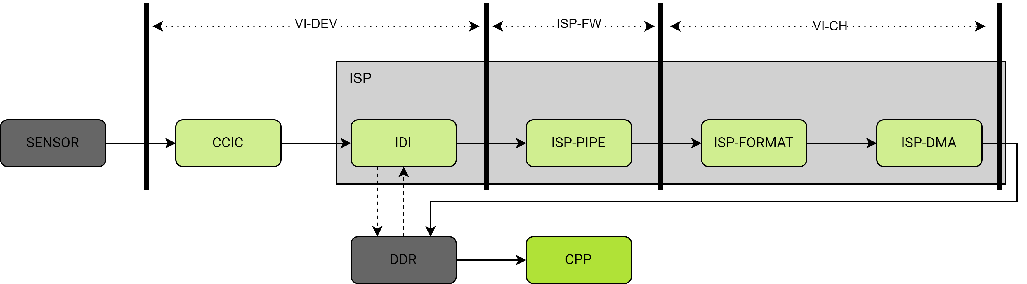
Description of Core Functional Modules:
-
SENSOR (Image Sensor)
- Converts light from the lens into electrical signals, then uses internal AD conversion to generate digital signals, and finally outputs MIPI RAW data.
-
CCIC (CMOS Camera Image Controller)
- Parses and receives the MIPI data sent from the sensor.
-
IDI (ISP Data Input Module)
- Receives data from CCIC or reads data from DDR and sends it to the ISP Pipeline
- Also stores CCIC data into DDR
-
ISP-PIPE (Image Processing Pipeline)
- Internal ISP hardware pipeline
- Performs a series of image-related algorithm processing
-
ISP-FORMAT (Output Format Control)
- Internal ISP hardware module
- Controls the output image format
-
ISP-DMA (Direct Memory Access)
- Internal ISP hardware module
- Writes image data into DDR
-
CPP (Post-Processing Unit)
- Performs image noise reduction and edge enhancement.
System Data Flow Description
Raw light signal → SENSOR (photoelectric conversion) → CCIC (data reception) → IDI (data routing) → ISP-PIPE (image processing) → ISP-FORMAT (format conversion) → ISP-DMA (memory write) → CPP (post-processing) → Final output
Camera Driver Framework
Note:
This section is for informational purposes only. During actual development, except for the sensor driver part, the rest of the content is typically not involved in the sensor bring-up process.
Framework Overview
The SpacemiT camera driver is implemented based on the Linux kernel V4L2 framework. Its main functionalities include:
- Hardware register access
- Interrupt handling
- Buffer and event management
- Providing SDK interfaces to user space
The relationships among the various modules within the Camera subsystem are shown in the diagram below:
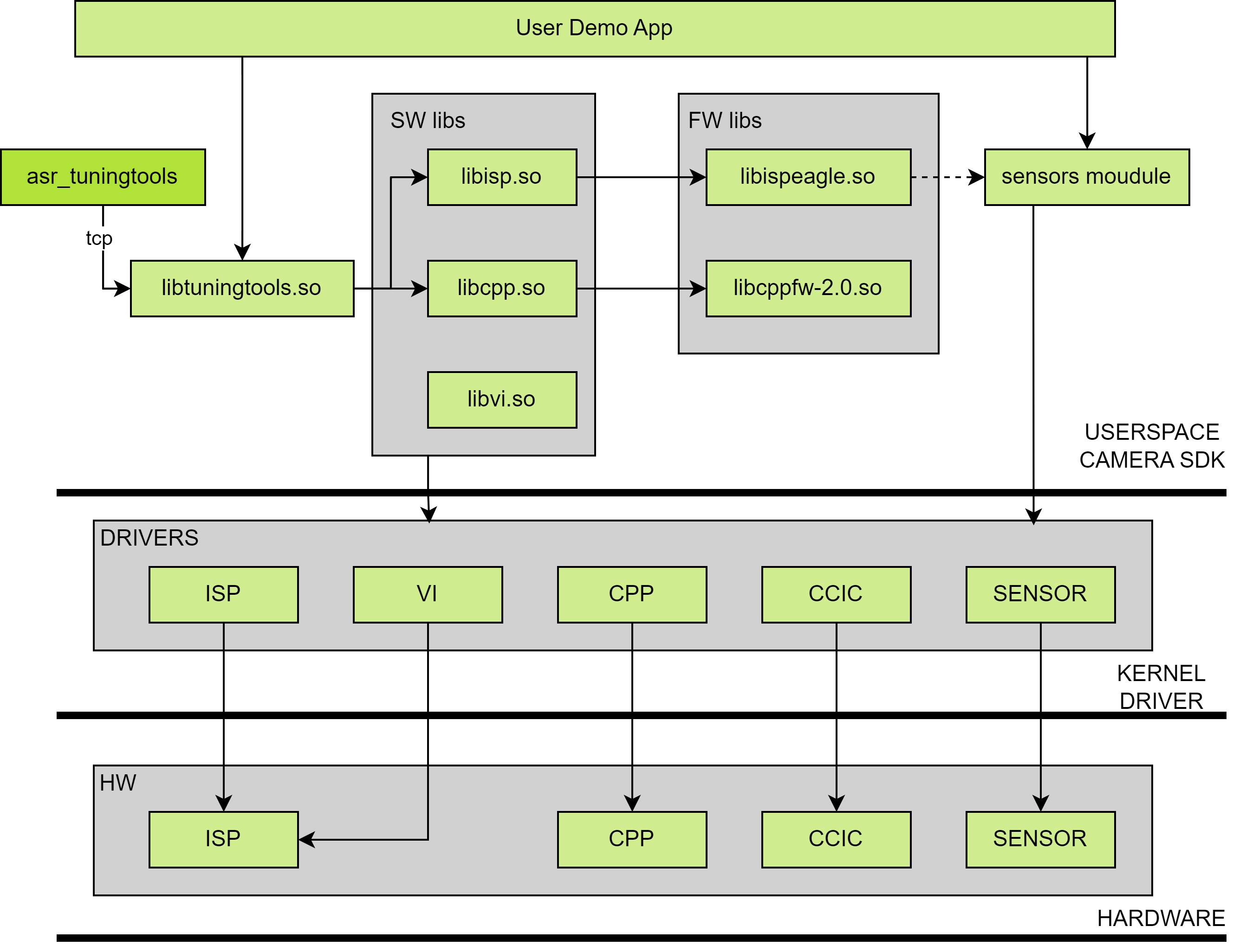
From a software call perspective, the architecture is divided into the following three layers from top to bottom:
-
Userspace: Runs in user space.
- Includes ISP, CPP, VI, and tuning tools software libraries, firmware libraries for ISP and CPP, and sensor module source code.
- Users primarily interact with camera applications by calling the interfaces of the ISP, CPP, VI, and sensor modules. Interfaces in the firmware libraries are called internally by the ISP and CPP software libraries.
- Additionally, if users need to use ASR's tuning tool to adjust the image quality of ISP/CPP output, they must call the interfaces of
libtuningtools.soin their application to create a tuning server.
-
Kernel Space:
- Runs in kernel space.
- Primarily provides drivers for ISP, CPP, VI, CCIC, and sensors.
-
Hardware Layer:
- The hardware modules that are directly accessed by the drivers.
For sensor bring-up needs, the main focus should be on the APP demo implementation in userspace, i.e., how to call SDK interfaces to fulfill specific application scenarios.
Source Code Structure
~/k1x/linux-6.6/drivers/media/platform/spacemit/camera$ tree
.
|-- built-in.a
|-- cam_ccic
|   |-- ccic_drv.c
|   |-- ccic_drv.h
|   |-- ccic_hwreg.c
|   |-- ccic_hwreg.h
|   |-- csiphy.c
|   |-- csiphy.h
|   |-- dptc_drv.c
|   |-- dptc_drv.h
|   `-- dptc_pll_setting.h
|-- cam_cpp
|   |-- cpp_compat_ioctl32.c
|   |-- cpp_compat_ioctl32.h
|   |-- cpp_dmabuf.c
|   |-- cpp_dmabuf.h
|   |-- cpp_iommu.c
|   |-- cpp_iommu.h
|   |-- cpp-v2p0.c
|   |-- k1x_cpp.c
|   |-- k1x_cpp.h
|   |-- regs-cpp-iommu.h
|   |-- regs-cpp-v2p0.h
|   `-- regs-fbc-v2p0.h
|-- cam_isp
|   |-- k1x_isp_drv.c
|   |-- k1x_isp_drv.h
|   |-- k1x_isp_pipe.c
|   |-- k1x_isp_pipe.h
|   |-- k1x_isp_reg.c
|   |-- k1x_isp_reg.h
|   |-- k1x_isp_statistic.c
|   `-- k1x_isp_statistic.h
|-- cam_plat
|   |-- cam_plat.c
|   `-- cam_plat.h
|-- cam_sensor
|   |-- cam_sensor.c
|   `-- cam_sensor.h
|-- cam_util
|   |-- cam_dbg.c
|   `-- cam_dbg.h
|-- Kconfig
|-- Makefile
|-- modules.order
`-- vi
    |-- cam_block.c
    |-- cam_block.h
    |-- k1xvi
    |   |-- fe_isp.c
    |   |-- fe_isp.h
    |   |-- hw-seq
    |   |   |-- hw_ccic.c
    |   |   |-- hw_ccic.h
    |   |   |-- hw_dma.c
    |   |   |-- hw_dma.h
    |   |   |-- hw_iommu.c
    |   |   |-- hw_iommu.h
    |   |   |-- hw_isp.c
    |   |   |-- hw_isp.h
    |   |   |-- hw_postpipe.c
    |   |   |-- hw_postpipe.h
    |   |   |-- hw_reg.h
    |   |   `-- hw_reg_iommu.h
    |   |-- k1xvi.c
    |   `-- k1xvi.h
    |-- mlink.c
    |-- mlink.h
    |-- spacemit_videobuf2.h
    |-- subdev.c
    |-- subdev.h
    |-- vdev.c
    |-- vdev.h
    |-- vsensor.c
    `-- vsensor.h
Driver Configuration
Run the following command to enter the kernel configuration menu of buildroot:
make linux-menuconfig
Locate the corresponding macro configurations and enable them one by one.
 Symbol: SPACEMIT_K1X_CAMERA_V2 [=y]                                                                                                                                                                                                                                                   │
  │ Type  : tristate                                                                                                                                                                                                                                                                      │
  │ Defined at drivers/media/platform/spacemit/camera/Kconfig:8                                                                                                                                                                                                                           │
  │   Prompt: SPACEMIT K1X camera and video capture V2 support                                                                                                                                                                                                                            │
  │   Depends on: MEDIA_SUPPORT [=y] && MEDIA_PLATFORM_SUPPORT [=y] && MEDIA_PLATFORM_DRIVERS [=y]                                                                                                                                                                                        │
  │   Location:                                                                                                                                                                                                                                                                           │
  │     -> Device Drivers                                                                                                                                                                                                                                                                 │
  │       -> Multimedia support (MEDIA_SUPPORT [=y])                                                                                                                                                                                                                                      │
  │         -> Media drivers                                                                                                                                                                                                                                                              │
  │           -> Media platform devices (MEDIA_PLATFORM_DRIVERS [=y])                                                                                                                                                                                                                     │
  │ (1)         -> SPACEMIT K1X camera and video capture V2 support (SPACEMIT_K1X_CAMERA_V2 [=y])                                                                                                                                                                                         │
  │ Selects: MEDIA_CONTROLLER [=y] && VIDEO_V4L2_SUBDEV_API [=y]
The above shows the path for the CONFIG_SPACEMIT_K1X_CAMERA_V2 configuration. After selecting and enabling it, enable the remaining Camera-related configurations as well.
Once all configurations are enabled and saved, you can verify them by checking the ./output/k1/build/linux-custom/.config file, as shown below.
#
# SPACEMIT K1X Camera And Video V2
#
CONFIG_SPACEMIT_K1X_CAMERA_V2=y
CONFIG_SPACEMIT_K1X_CCIC_V2=y
CONFIG_SPACEMIT_K1X_VI_V2=y
CONFIG_SPACEMIT_K1X_VI_IOMMU=y
CONFIG_SPACEMIT_K1X_ISP_V2=y
CONFIG_SPACEMIT_K1X_CPP_V2=y
CONFIG_SPACEMIT_K1X_SENSOR_V2=y
Sensor Driver
Sensor-related driver code is located in the linux/drivers/media/platform/spacemit/camera/cam_sensor directory. After loading the driver, device nodes /dev/cam_sensorX will be created in the system, where X is the sensor device ID, also referred to as the camera ID below.
The Sensor driver is a lightweight character driver, mainly providing the following functions:
- Controlling the sensor power.
- Encapsulating I2C read/write operations.
During the bring-up process (initial startup or initialization), pay special attention to the following two functions:
- The
camsnr_of_parse()function indicates the supported properties parsed from the sensor DTS node. - The
cam_sensor_power_set()function defines the power on/off sequence and checks whether it matches the new sensor's operation process.
In practice, the power-on and power-off sequences should be adjusted based on the specific sensor hardware design and datasheet:
-
When operations are consistent
If the new sensor's power-on/off sequences are consistent with existing code (e.g.,imx135sensor), you can directly callioctl CAM_SENSOR_UNRESETto complete power-on. For example:- Call
sensor_hw_unresetin theimx135_initfunction to power on. - Call
sensor_hw_resetin theimx135_deinitfunction to power off.
- Call
-
When operations differ
If the new sensor's power-on/off sequences differ from existing code (e.g.,gc2375hsensor), you need to define custom power-on/off functions by leveraging the sensor character driver'sioctlinterface. For example:- Define
gc2375h_power_onfunction to implement the power-on procedure required by thegc2375hsensor. - Define
gc2375h_power_offfunction to implement the power-off procedure required by thegc2375hsensor.
- Define
DTS Introduction
The DTS configurations related to the Camera are mainly distributed across the following files (there may be slight differences between different solutions):
Path: arch/riscv/boot/dts/spacemit/k1-x-camera-sensor.dtsi
Purpose: Configuration information for various sensors

Path: arch/riscv/boot/dts/spacemit/k1-x-camera-sdk.dtsi
Purpose: Configuration information for CCIC, CSIPHY, ISP, VI, and CPP

Path: arch/riscv/boot/dts/spacemit/k1-x_pinctrl.dtsi
Purpose: Pinctrl configuration information required by the camera

Path: arch/riscv/boot/dts/spacemit/k1-xxxx.dts
Purpose: Board-related configuration for different solutions
Pinctrl
Currently, only the camera MCLK pin configuration is defined through pinctrl.
路径: arch/riscv/boot/dts/spacemit/k1-x_pinctrl.dtsi

pinctrl_camera0: camera0_grp {
    pinctrl-single,pins =<
        K1X_PADCONF(GPIO_53,    MUX_MODE1, (EDGE_NONE | PULL_DOWN | PAD_1V8_DS2))  /* cam_mclk0 */
    >;
};

pinctrl_camera1: camera1_grp {
    pinctrl-single,pins =<
        K1X_PADCONF(GPIO_58,    MUX_MODE1, (EDGE_NONE | PULL_DOWN | PAD_1V8_DS2))  /* cam_mclk1 */
    >;
};

pinctrl_camera2: camera2_grp {
    pinctrl-single,pins =<
        K1X_PADCONF(GPIO_120,    MUX_MODE1, (EDGE_NONE | PULL_DOWN | PAD_1V8_DS2))  /* cam_mclk2 */
    >;
};

Path: arch/riscv/boot/dts/spacemit/k1-x-camera-sensor.dtsi

/* imx315 */
backsensor: cam_sensor@0 {
    ......

    pinctrl-names = "default";
    pinctrl-0 = <&pinctrl_camera0>;

    ......
    status = "okay";
};
GPIO
Refer to the development board schematic
On the development board, MIPI CSI interfaces (such as CSI0, CSI1, CSI2) typically use GPIOs to control the camera module's reset and power signals. Usually, at least one set of GPIOs is assigned for these functions. For example, assume the reset GPIO for the MIPI CSI0 interface is GPIO 111, the power GPIO is GPIO 113, and this interface connects to the camera0:imx135 camera module (it is recommended that the camera ID matches the MIPI CSI interface number).
The backsensor configuration in the solution DTS is as follows.
Path: arch/riscv/boot/dts/spacemit/k1-xxxx.dts

// To improve efficiency, GPIO should be used as follows
// The '2' following GPIO_111 indicates the number of consecutive GPIOs to configure; in this example, it means GPIO_111 and GPIO_112.
&pinctrl {
        pinctrl-single,gpio-range = <
                &range GPIO_111 2 (MUX_MODE0 | EDGE_NONE | PULL_DOWN | PAD_1V8_DS2)
        >;
};

&gpio {
        gpio-ranges = <
                &pinctrl 111  GPIO_111  2
        >;
};

/* imx315 */
&backsensor {
        pwdn-gpios = <&gpio 113 0>;
        reset-gpios = <&gpio 111 0>;

        ......
        status = "okay";
};

Path: arch/riscv/boot/dts/spacemit/k1-x-camera-sensor.dtsi
//camera ID0 corresponds to imx135
&soc {

    /*imx315 */
    backsensor: cam sensor@0 {
        cell-index =<0>;
        status ="okay";
    };
};
pwdn-gpios and reset-gpios relate to the power supply configuration of the sensor module. The sensor driver uses these configurations to perform sensor power on/off and reset operations. Different sensor modules may have different configurations, so careful modification is required during bring up.
Sensor DTS Configuration
The sensor configurations defined inside k1-x-camera-sensor.dtsi are as follows:
        /* imx315 */
        backsensor: cam_sensor@0 {
                cell-index = <0>;
                twsi-index = <0>;
                dphy-index = <0>;
                compatible = "spacemit,cam-sensor";
                clocks = <&ccu CLK_CAMM0>;
                clock-names = "cam_mclk0";

                /* This section has been moved to the top-level DTS.
                afvdd28-supply = <&ldo_12>;
                avdd28-supply = <&ldo_10>;
                dvdd12-supply = <&ldo_20>;
                iovdd18-supply = <&ldo_11>;
                cam-supply-names = "afvdd28", "avdd28", "dvdd12", "iovdd18";
                */

                ......
                status = "okay";
        };
cell-indexspecifies the device ID of the sensor, which must exactly match the sensor device ID used by the upper layers.twsi-indexspecifies the ID of the I2C core used by the sensor. Before use, ensure the corresponding I2C bus DTS configuration is enabled. For details, please refer to the I2C section.dphy-indexindicates the PHY ID used by the sensor.clocks/clock-namesindicates the clock source of the MCLK used by the sensor.
Bring up Summary
During the bring up process, driver modifications mainly involve the following steps:
-
Check the hardware platform’s CSI PHY and CCIC configuration
If this is the first time bringing up the sensor module on the hardware platform, check whether thecsiphyandccicconfigurations defined ink1-x-camera-sdk.dtsiare correct. If the module has already been brought up before, or the configurations are correct, this step can be skipped. -
Modify sensor configuration
Modify the sensor configuration defined ink1-x-camera-sensor.dtsior the top-level DTS file according to the requirements of the new sensor to adapt to the new sensor. -
Check and adjust sensor driver’s power management flow
Verify whether the power on/off flow in the sensor driver fits the new sensor. If not, modify the sensor driver code as needed to ensure the power management process complies with the new sensor’s requirements.
User Layer cam_sensors Library
In the user layer, operations on sensor modules are compiled and encapsulated in the libcam_sensors library. The source code of this module is located at xxxx/package-src/k1x-cam/sensors.
Common Operations
The common sensor operation code resides in the sensor subdirectory. The cam_sensor.c file defines operations shared by all sensors and usually does not require modification. For specific sensor models, the xxx_sensor.c file defines that sensor’s operations.
- If the
sensorsubdirectory already contains thexxx_sensor.cfile for the sensor to be brought up, no modification is needed; - If not, a new
xxx_sensor.cfile needs to be added for the new sensor.
Operation Function Set
The xxx_sensor.c file defines the struct SENSOR_OBJ structure, which serves as the external operation function set for the sensor. This structure contains the following members:
-
const char* name;
The name of the sensor. -
int (*pfnInit)(void** pHandle, int sns_id, uint8_t sns_addr);
Sensor initialization. -
int (*pfnDeinit)(void* handle);
Sensor deinitialization. -
int (*pfnGlobalConfig)(void* handle, SENSOR_WORK_INFO_S* work_info);
Globally configure the sensor according to the input work info. -
int (*pfnSetParam)(void* handle, const SENSOR_INIT_ATTR_S* init_attr);
Set sensor 3A parameters before initialization. -
int (*pfnStreamOn)(void* handle);
Start the sensor data stream. -
int (*pfnStreamOff)(void* handle);
Stop the sensor data stream. -
int (*pfnGetSensorOps)(void* handle, ISP_SENSOR_REGISTER_S* pSensorFuncOps);
Get the callback operation function set that the sensor registers to the ISP. -
int (*pfnDetectSns)(void* handle, SENSOR_VENDOR_ID_S* vendor_id);
Detect the sensor. -
int (*pfnWriteReg)(void* handle, uint16_t regAddr, uint16_t value);
Write to a register. -
int (*pfnReadReg)(void* handle, uint16_t regAddr, uint16_t* value);
Read from a register.
ISP Callback Operation Function Set
The xxx_sensor.c file defines the struct spmISP_SENSOR_FUNC_S structure, which serves as the callback function set that the sensor registers to the ISP. This structure contains the following members:
-
int (*pfn_sensor_write_reg)(void*snsHandle, uint32_t regAddr, uint32_t value);
Write to sensor register. -
int (*pfn_sensor_get_isp_default)(void*snsHandle, uint32_t u32ChanelId, uint32_t camScene, ISP_SENSOR_DEFAULT_S *pstDef);
Get the tuning data parameters used by the ISP. -
int (*pfn_sensor_get_isp_black_level)(void*snsHandle, uint32_t u32ChanelId, ISP_SENSOR_BLACK_LEVEL_S *pstBlackLevel);
Get the sensor’s default black level. -
int (*pfn_sensor_get_reg_info)(void*snsHandle, ISP_SENSOR_REGS_INFO_S *pstSensorRegsInfo);
Get the basic configuration for sensor register operations. -
int (*pfn_sensor_dump_info)(void*snsHandle);
Dump sensor information required for debugging. -
int (*pfn_sensor_group_regs_start)(void*snsHandle);
Start operation for the sensor group writer. -
int (*pfn_sensor_group_regs_done)(void*snsHandle);
End operation for sensor group writer.
ISP AE Callback Operation Function Set
The xxx_sensor.c file defines the struct spmISP_SENSOR_AE_FUNC_S structure as the callback function set that the sensor registers to the ISP AE algorithm. The structure contains the following members:
-
int (*pfn_sensor_get_ae_default)(void* snsHandle, uint32_t u32ChanelId, ISP_SENSOR_AE_DEFAULT_S *pstSensorAeDft);
Get the sensor's default AE (Auto Exposure) parameters. -
int (*pfn_sensor_fps_set)(void* snsHandle, float f32Fps);
Set the sensor's frames per second (fps). -
int (*pfn_sensor_get_expotime_by_fps)(void* snsHandle, float f32Fps);
Retrieve the maximum exposure time based on the configured fp. -
int (*pfn_sensor_expotime_update)(void* snsHandle, uint32_t u32ChanelId, uint32_t u32ExpoTime, ISP_SENSOR_VTS_INFO_S *pstSensorVtsInfo);
Update sensor and exposure time related register values, only updating software values without writing to registers physically. -
int (*pfn_sensor_gain_update)(void* snsHandle, uint32_t u32ChanelId, uint32_t *pAgainVal, uint32_t *pDgainVal);
Update sensor and gain related register values, only updating software values without writing to registers physically. -
int (*pfn_get_aelib_default_settings)(void* snsHandle, uint32_t u32ChanelId, AE_LIB_DEFAULT_SETTING_S **ppstAeLibDefault);
Get the tuning data parameters used by the AE algorithm of the specified ISP pipeline.
ISP AWB Callback Operation Function Set
The xxx_sensor.c file defines the struct spmISP_SENSOR_AWB_FUNC_S structure as the callback function set that the sensor registers to the ISP AWB algorithm. The structure contains the following members:
-
int (*pfn_sensor_get_awb_default)(void* snsHandle, uint32_t u32ChanelId, ISP_SENSOR_AWB_DEFAULT_S *pstSensorAwbDft);
Get the sensor's default AWB (Auto White Balance) parameters. -
int (*pfn_get_awblib_default_settings)(void* snsHandle, uint32_t u32ChanelId, AWB_LIB_DEFAULT_SETTING_S **ppstAwbLibDefault);
Get the tuning data parameters used by the AWB algorithm of the specified ISP pipeline.
Differentiated Operations
Even when the same sensor is used, different modules in different projects may require various differentiated configurations, such as sensor settings or adapted ISP tuning data. These differentiated codes reside in the module subdirectory. For a new sensor module, you need to create a subdirectory to define related operations.
Inside the subdirectory, the xxx_setting.h file defines several sets of sensor settings supported by the current module sensor.
The xxx.c file in the subdirectory defines the struct MODULE_OBJ structure, which serves as the operation function set exposed by the module. This structure contains the following members:
-
const char* name;
The module name. -
int (*pfnGetsnrCapSize)(int32_t* capArraySize);
Get the number of working modes of the module sensor (corresponding one-to-one with sensor settings). -
int (*pfnGetsnrCapbility)(int32_t capArraySize, SENSOR_CAPABILITY_S* sensor_capability);
Get the capabilities of all working modes of the module sensor (corresponding one-to-one with sensor settings). -
int (*pfnGetSnrWorkInfo)(int32_t work_mode, SENSOR_WORK_INFO_S* snr_info);
Get the capability of the specified working mode of the module sensor (corresponding one-to-one with sensor settings). -
int (*pfnGetSnrVendorId)(SENSOR_VENDOR_ID_S* vendor_id);
Get the vendor ID of the module sensor. -
int (*pfnGetSnrI2cAddr)(uint8_t* i2c_addr);
Get the I2C address of the module sensor.
SENSORS_MODULE_OBJ_S
Each sensor module consists of the sensor, lens motor, and flash. In the header file cam_sensors_module_list.h, the structure struct SENSORS_MODULE_OBJ is defined, which specifies the components of a sensor module and contains the following four parts:
-
MODULE_OBJ_S* module_obj_p;
The module sensor, corresponding to themodulesubdirectory. The module sensor's name is the overall name of the sensor module. -
SENSOR_OBJ_S* sensor_obj_p;
The common sensor operations set, corresponding to thesensorsubdirectory. -
VCM_OBJ_S* vcm_obj_p;
The motor, corresponding to thevcmsubdirectory. -
FLASH_OBJ_S* flash_obj_p;
The flash, corresponding to theflashsubdirectory.
Whenever adding a new sensor module, you need to add it into the SENSORS_MODULE_OBJ_S sensors_module_list[] array. This list represents all the sensor modules currently supported by the software.
Bring up Summary
During the bring-up process, the modifications to the User-level cam_sensors library mainly include the following steps:
- Check within the
sensorsubdirectory whether the files related to the sensor to be brought up already exist. If not, add the common operation code for the new sensor. - In the
modulesubdirectory, add a subdirectory for the differentiated operations of the new sensor, primarily for its sensor settings and tuning data. - Add the new module to the
SENSORS_MODULE_OBJ_S sensors_module_list[]array. - (If applicable) Add the new source files to the
CUR_SOURCEvariable in the Makefile.
User-Level Demo Examples
Source Code Structure
lizhirong@lnode1:~/buildroot-sdk/package-src/k1x-cam$ tree
.
|-- CMakeLists.txt
|-- Config.in
|-- debian
|   |-- bianbu.conf
|   |-- changelog
|   |-- compat
|   |-- control
|   |-- copyright
|   |-- README.Debian
|   |-- rules
|   |-- source
|   |   |-- format
|   |   `-- local-options
|   `-- watch
|-- demo
|   |-- camtest.sh
|   |-- cfgs
|   |   |-- 0
|   |   |   |-- camtest_sensor0_mode0.json
|   |   |   |-- camtest_sensor0_mode1.json
|   |   |   |-- camtest_sensor0_mode2.json
|   |   |   |-- camtest_sensor1_mode0.json
|   |   |   `-- camtest_sensor2_mode0.json
|   |   |-- 1
|   |   |   |-- camtest_main_aux.json
|   |   |   `-- camtest_main_front.json
|   |   |-- 2
|   |   |   |-- camtest_sensor0_mode0.json
|   |   |   |-- camtest_sensor1_mode0.json
|   |   |   `-- camtest_sensor2_mode0.json
|   |   |-- 3
|   |   |   |-- camtest_sensor0_mode0.json
|   |   |   |-- camtest_sensor1_mode0.json
|   |   |   `-- camtest_sensor2_mode0.json
|   |   |-- 4
|   |   |   |-- camtest_sensor0_mode0_nv12.json
|   |   |   |-- camtest_sensor0_mode0_p010.json
|   |   |   |-- camtest_sensor0_mode0_p210.json
|   |   |   |-- camtest_sensor0_mode0_rgb565.json
|   |   |   |-- camtest_sensor0_mode0_rgb888.json
|   |   |   `-- camtest_sensor0_mode0_y210.json
|   |   |-- 5
|   |   |   `-- camtest_1920x1080_raw12.json
|   |   |-- 6
|   |   |   `-- camtest_1920x1080.json
|   |   `-- files
|   |       |-- 1920x1080_raw12_long_packed.vrf
|   |       `-- cpp_case_in_data
|   |           `-- 1920x1080
|   |               |-- L0.nv12
|   |               |-- L1.raw
|   |               |-- L2.raw
|   |               |-- L3.raw
|   |               `-- L4.raw
|   |-- CMakeLists.txt
|   |-- config.c
|   |-- config.h
|   |-- cpp_common.c
|   |-- cpp_common.h
|   |-- dual_pipeline_capture_test.c
|   |-- dual_pipeline_capture_test.h
|   |-- extern
|   |   |-- cjson.c
|   |   |-- cjson.h
|   |   |-- sstr.c
|   |   `-- sstr.h
|   |-- gst_cam_api.c
|   |-- gst_cam_api.h
|   |-- include
|   |   |-- bufferPool.c
|   |   |-- bufferPool.h
|   |   |-- cam_interface.h
|   |   |-- dmabufheap
|   |   |   |-- BufferAllocator.cpp
|   |   |   |-- BufferAllocator.h
|   |   |   |-- BufferAllocatorWrapper.cpp
|   |   |   |-- BufferAllocatorWrapper.h
|   |   |   `-- dmabufheap-defs.h
|   |   |-- dmabufheapAllocator.c
|   |   `-- dmabufheapAllocator.h
|   |-- main.c
|   |-- online_pipeline_test.c
|   |-- online_pipeline_test.h
|   |-- sensor_common.c
|   |-- sensor_common.h
|   |-- tuning_server.c
|   |-- tuning_server.h
|   |-- utils
|   |   |-- cam_list.c
|   |   |-- cam_list.h
|   |   |-- cam_log.h
|   |   |-- condition.c
|   |   `-- condition.h
|   |-- viisp_common.c
|   `-- viisp_common.h
|-- libs
|   |-- include
|   |   |-- cam_cpp.h
|   |   |-- cam_module_interface.h
|   |   |-- CPPGlobalDefine.h
|   |   |-- ISPGlobalDefine.h
|   |   |-- spm_cam_isp.h
|   |   |-- spm_cam_tuning_assistant.h
|   |   |-- spm_cam_vi.h
|   |   |-- spm_comm_cam.h
|   |   |-- spm_comm_tuning.h
|   |   |-- spm_comm_vi.h
|   |   |-- spm_isp_comm.h
|   |   `-- spm_isp_sensor_comm.h
|   `-- lib64
|       |-- libcppfw-2.0.so
|       |-- libcpp.so
|       |-- libispeagle.so
|       |-- libisp.so
|       |-- libtuningtools.so
|       `-- libvi.so
|-- pkgconfig
|   `-- k1x-cam.pc.cmake
`-- sensors
    |-- camera_base.h
    |-- cam_log.h
    |-- cam_sensors_module.c
    |-- cam_sensors_module.h
    |-- cam_sensors_module_list.h
    |-- cam_sensor_uapi.h
    |-- cam_spm_otp_handle.c
    |-- cam_spm_otp_handle.h
    |-- CMakeLists.txt
    |-- flash
    |   |-- aw36515_led.c
    |   |-- cam_led.h
    |   `-- flash_aw36515.h
    |-- include
    |   |-- spm_cam_sensors.h
    |   `-- spm_comm_sensors.h
    |-- module
    |   |-- common
    |   |   |-- common_FlickerSetting.h
    |   |   `-- common_rawhdr_default_setting.h
    |   |-- gc2375h_spm
    |   |   |-- gc2375h_spm.c
    |   |   |-- gc2375h_spm.h
    |   |   |-- gc2375h_spm_rear_secondary_cpp_nightshot_setting.h
    |   |   |-- gc2375h_spm_rear_secondary_cpp_preview_setting.h
    |   |   |-- gc2375h_spm_rear_secondary_cpp_snapshot_setting.h
    |   |   |-- gc2375h_spm_rear_secondary_cpp_video_setting.h
    |   |   |-- gc2375h_spm_rear_secondary_isp_setting.h
    |   |   |-- gc2375h_spm_rear_secondary_isp_setting_video.h
    |   |   |-- gc2375h_spm_rear_secondary_nightshot_setting.h
    |   |   `-- gc2375h_spm_setting.h
    |   |-- gc5035_spm
    |   |   |-- gc5035_spm.c
    |   |   |-- gc5035_spm.h
    |   |   |-- gc5035_spm_rear_secondary_cpp_nightshot_setting.h
    |   |   |-- gc5035_spm_rear_secondary_cpp_preview_setting.h
    |   |   |-- gc5035_spm_rear_secondary_cpp_snapshot_setting.h
    |   |   |-- gc5035_spm_rear_secondary_cpp_video_setting.h
    |   |   |-- gc5035_spm_rear_secondary_isp_setting.h
    |   |   |-- gc5035_spm_rear_secondary_isp_setting_video.h
    |   |   |-- gc5035_spm_rear_secondary_nightshot_setting.h
    |   |   `-- gc5035_spm_setting.h
    |   |-- imx135_spm
    |   |   |-- imx135_spm.c
    |   |   |-- imx135_spm.h
    |   |   |-- imx135_spm_rear_primary_cpp_nightshot_setting.h
    |   |   |-- imx135_spm_rear_primary_cpp_preview_setting.h
    |   |   |-- imx135_spm_rear_primary_cpp_snapshot_setting.h
    |   |   |-- imx135_spm_rear_primary_cpp_video_setting.h
    |   |   |-- imx135_spm_rear_primary_isp_setting.h
    |   |   |-- imx135_spm_rear_primary_isp_setting_video.h
    |   |   |-- imx135_spm_rear_primary_nightshot_setting.h
    |   |   `-- imx135_spm_setting.h
    |   |-- os05a10_spm
    |   |   |-- os05a10_spm.c
    |   |   |-- os05a10_spm.h
    |   |   `-- os05a10_spm_setting.h
    |   |-- ov08d10_spm
    |   |   |-- ov08d10_spm.c
    |   |   |-- ov08d10_spm_front_cpp_nightshot_setting.h
    |   |   |-- ov08d10_spm_front_cpp_preview_setting.h
    |   |   |-- ov08d10_spm_front_cpp_snapshot_setting.h
    |   |   |-- ov08d10_spm_front_cpp_video_setting.h
    |   |   |-- ov08d10_spm_front_isp_setting.h
    |   |   |-- ov08d10_spm_front_isp_setting_video.h
    |   |   |-- ov08d10_spm_front_nightshot_setting.h
    |   |   |-- ov08d10_spm.h
    |   |   `-- ov08d10_spm_setting.h
    |   |-- ov13b10_spm
    |   |   |-- ov13b10_spm.c
    |   |   |-- ov13b10_spm.h
    |   |   |-- ov13b10_spm_rear_primary_cpp_nightshot_setting.h
    |   |   |-- ov13b10_spm_rear_primary_cpp_preview_setting.h
    |   |   |-- ov13b10_spm_rear_primary_cpp_snapshot_setting.h
    |   |   |-- ov13b10_spm_rear_primary_cpp_video_setting.h
    |   |   |-- ov13b10_spm_rear_primary_isp_setting.h
    |   |   |-- ov13b10_spm_rear_primary_isp_setting_video.h
    |   |   |-- ov13b10_spm_rear_primary_nightshot_setting.h
    |   |   `-- ov13b10_spm_setting.h
    |   |-- ov16a10_spm
    |   |   |-- ov16a10_spm.c
    |   |   |-- ov16a10_spm.h
    |   |   |-- ov16a10_spm_rear_primary_cpp_nightshot_setting.h
    |   |   |-- ov16a10_spm_rear_primary_cpp_preview_setting.h
    |   |   |-- ov16a10_spm_rear_primary_cpp_snapshot_setting.h
    |   |   |-- ov16a10_spm_rear_primary_cpp_video_setting.h
    |   |   |-- ov16a10_spm_rear_primary_isp_setting.h
    |   |   |-- ov16a10_spm_rear_primary_isp_setting_video.h
    |   |   |-- ov16a10_spm_rear_primary_nightshot_setting.h
    |   |   `-- ov16a10_spm_setting.h
    |   `-- s5k5e3yx_spm
    |       |-- s5k5e3yx_spm.c
    |       |-- s5k5e3yx_spm_front_cpp_nightshot_setting.h
    |       |-- s5k5e3yx_spm_front_cpp_preview_setting.h
    |       |-- s5k5e3yx_spm_front_cpp_snapshot_setting.h
    |       |-- s5k5e3yx_spm_front_cpp_video_setting.h
    |       |-- s5k5e3yx_spm_front_isp_setting.h
    |       |-- s5k5e3yx_spm_front_isp_setting_video.h
    |       |-- s5k5e3yx_spm_front_nightshot_setting.h
    |       |-- s5k5e3yx_spm.h
    |       `-- s5k5e3yx_spm_setting.h
    |-- sensor
    |   |-- cam_sensor.c
    |   |-- cam_sensor.h
    |   |-- gc2375h_sensor.c
    |   |-- gc5035_sensor.c
    |   |-- imx135_sensor.c
    |   |-- os05a10_sensor.c
    |   |-- ov08d10_sensor.c
    |   |-- ov13b10_sensor.c
    |   |-- ov16a10_sensor.c
    |   `-- s5k5e3yx_sensor.c
    |-- test
    |   |-- cam_sensors_test.c
    |   `-- CMakeLists.txt
    `-- vcm
        |-- cam_vcm.c
        |-- cam_vcm.h
        |-- dw9714_vcm.c
        |-- dw9763_vcm.c
        |-- gt9772_vcm.c
        `-- i2c
            |-- i2c_common.c
            `-- i2c_common.h
Demo Compilation
Clean the application
~/buildroot-sdk$ make k1x-cam-dirclean
Compile the application
~/buidroot-sdk$ make k1x-cam
Rebuild the application
~/buildroot-sdk$ make k1x-cam-rebuild
From the output log, you can see the generated files:
>>> k1x-cam 1.0.0 Installing to target
GIT_DIR=. PATH="/home/lizhirong/buildroot-sdk/output/k1/host/bin:/home/lizhirong/buildroot-sdk/output/k1/host/sbin:/home/lizhirong/k1x/out/toolchain/bin:/home/lizhirong/k1x/vendor/tool/sign-tools:/home/lizhirong/bin/spacemit-gcc-linux-glibc-x86_64-jdsk-v0.1.8-20230609T064501/bin:/home/lizhirong/.local/bin:/home/lizhirong/bianbu-dev/scripts:/usr/share/safe-rm/bin:/usr/local/sbin:/usr/local/bin:/usr/sbin:/usr/bin:/sbin:/bin:/usr/games:/usr/local/games:/snap/bin:/home/lizhirong/bianbu-devscripts"  /usr/bin/make -j65  DESTDIR=/home/lizhirong/buildroot-sdk/output/k1/target install/fast -C /home/lizhirong/buildroot-sdk/output/k1/build/k1x-cam-1.0.0/
Install the project...
-- Install configuration: "Release"
-- Installing: /home/lizhirong/buildroot-sdk/output/k1/target/usr/lib/libsdkcam.so
-- Set runtime path of "/home/lizhirong/buildroot-sdk/output/k1/target/usr/lib/libsdkcam.so" to ""
-- Installing: /home/lizhirong/buildroot-sdk/output/k1/target/usr/bin/cam-test
-- Set runtime path of "/home/lizhirong/buildroot-sdk/output/k1/target/usr/bin/cam-test" to ""
-- Up-to-date: /home/lizhirong/buildroot-sdk/output/k1/target/usr/lib
-- Installing: /home/lizhirong/buildroot-sdk/output/k1/target/usr/lib/libcpp.so
-- Installing: /home/lizhirong/buildroot-sdk/output/k1/target/usr/lib/libcppfw-2.0.so
-- Installing: /home/lizhirong/buildroot-sdk/output/k1/target/usr/lib/libtuningtools.so
-- Installing: /home/lizhirong/buildroot-sdk/output/k1/target/usr/lib/libisp.so
-- Installing: /home/lizhirong/buildroot-sdk/output/k1/target/usr/lib/libispeagle.so
-- Installing: /home/lizhirong/buildroot-sdk/output/k1/target/usr/lib/libvi.so
-- Installing: /home/lizhirong/buildroot-sdk/output/k1/target/usr/include
-- Installing: /home/lizhirong/buildroot-sdk/output/k1/target/usr/include/include
-- Installing: /home/lizhirong/buildroot-sdk/output/k1/target/usr/include/include/bufferPool.h
-- Installing: /home/lizhirong/buildroot-sdk/output/k1/target/usr/include/include/cam_interface.h
-- Installing: /home/lizhirong/buildroot-sdk/output/k1/target/usr/include/include/dmabufheapAllocator.h
-- Installing: /home/lizhirong/buildroot-sdk/output/k1/target/usr/include/include/dmabufheap
-- Installing: /home/lizhirong/buildroot-sdk/output/k1/target/usr/include/include/dmabufheap/dmabufheap-defs.h
-- Installing: /home/lizhirong/buildroot-sdk/output/k1/target/usr/include/include/dmabufheap/BufferAllocator.h
-- Installing: /home/lizhirong/buildroot-sdk/output/k1/target/usr/include/include/dmabufheap/BufferAllocatorWrapper.h
-- Installing: /home/lizhirong/buildroot-sdk/output/k1/target/usr/include/dual_pipeline_capture_test.h
-- Installing: /home/lizhirong/buildroot-sdk/output/k1/target/usr/include/config.h
-- Installing: /home/lizhirong/buildroot-sdk/output/k1/target/usr/include/cfgs
-- Installing: /home/lizhirong/buildroot-sdk/output/k1/target/usr/include/cfgs/files
-- Installing: /home/lizhirong/buildroot-sdk/output/k1/target/usr/include/cfgs/files/cpp_case_in_data
-- Installing: /home/lizhirong/buildroot-sdk/output/k1/target/usr/include/cfgs/files/cpp_case_in_data/1920x1080
-- Installing: /home/lizhirong/buildroot-sdk/output/k1/target/usr/include/cfgs/1
-- Installing: /home/lizhirong/buildroot-sdk/output/k1/target/usr/include/cfgs/2
-- Installing: /home/lizhirong/buildroot-sdk/output/k1/target/usr/include/cfgs/0
-- Installing: /home/lizhirong/buildroot-sdk/output/k1/target/usr/include/cfgs/3
-- Installing: /home/lizhirong/buildroot-sdk/output/k1/target/usr/include/cfgs/6
-- Installing: /home/lizhirong/buildroot-sdk/output/k1/target/usr/include/cfgs/4
-- Installing: /home/lizhirong/buildroot-sdk/output/k1/target/usr/include/cfgs/5
-- Installing: /home/lizhirong/buildroot-sdk/output/k1/target/usr/include/gst_cam_api.h
-- Installing: /home/lizhirong/buildroot-sdk/output/k1/target/usr/include/CMakeFiles
-- Installing: /home/lizhirong/buildroot-sdk/output/k1/target/usr/include/CMakeFiles/cam-test.dir
-- Installing: /home/lizhirong/buildroot-sdk/output/k1/target/usr/include/CMakeFiles/sdkcam.dir
-- Installing: /home/lizhirong/buildroot-sdk/output/k1/target/usr/include/CMakeFiles/sdkcam.dir/include
-- Installing: /home/lizhirong/buildroot-sdk/output/k1/target/usr/include/CMakeFiles/sdkcam.dir/include/dmabufheap
-- Installing: /home/lizhirong/buildroot-sdk/output/k1/target/usr/include/CMakeFiles/sdkcam.dir/utils
-- Installing: /home/lizhirong/buildroot-sdk/output/k1/target/usr/include/CMakeFiles/sdkcam.dir/extern
-- Installing: /home/lizhirong/buildroot-sdk/output/k1/target/usr/include/utils
-- Installing: /home/lizhirong/buildroot-sdk/output/k1/target/usr/include/utils/condition.h
-- Installing: /home/lizhirong/buildroot-sdk/output/k1/target/usr/include/utils/cam_list.h
-- Installing: /home/lizhirong/buildroot-sdk/output/k1/target/usr/include/utils/cam_log.h
-- Installing: /home/lizhirong/buildroot-sdk/output/k1/target/usr/include/online_pipeline_test.h
-- Installing: /home/lizhirong/buildroot-sdk/output/k1/target/usr/include/sensor_common.h
-- Installing: /home/lizhirong/buildroot-sdk/output/k1/target/usr/include/viisp_common.h
-- Installing: /home/lizhirong/buildroot-sdk/output/k1/target/usr/include/cpp_common.h
-- Installing: /home/lizhirong/buildroot-sdk/output/k1/target/usr/include/extern
-- Installing: /home/lizhirong/buildroot-sdk/output/k1/target/usr/include/extern/sstr.h
-- Installing: /home/lizhirong/buildroot-sdk/output/k1/target/usr/include/extern/cjson.h
-- Installing: /home/lizhirong/buildroot-sdk/output/k1/target/usr/include/tuning_server.h
-- Up-to-date: /home/lizhirong/buildroot-sdk/output/k1/target/usr/include
-- Installing: /home/lizhirong/buildroot-sdk/output/k1/target/usr/include/spm_cam_isp.h
-- Installing: /home/lizhirong/buildroot-sdk/output/k1/target/usr/include/spm_comm_vi.h
-- Installing: /home/lizhirong/buildroot-sdk/output/k1/target/usr/include/spm_comm_cam.h
-- Installing: /home/lizhirong/buildroot-sdk/output/k1/target/usr/include/spm_cam_vi.h
-- Installing: /home/lizhirong/buildroot-sdk/output/k1/target/usr/include/spm_isp_sensor_comm.h
-- Installing: /home/lizhirong/buildroot-sdk/output/k1/target/usr/include/spm_isp_comm.h
-- Installing: /home/lizhirong/buildroot-sdk/output/k1/target/usr/include/cam_module_interface.h
-- Installing: /home/lizhirong/buildroot-sdk/output/k1/target/usr/include/CPPGlobalDefine.h
-- Installing: /home/lizhirong/buildroot-sdk/output/k1/target/usr/include/spm_comm_tuning.h
-- Installing: /home/lizhirong/buildroot-sdk/output/k1/target/usr/include/spm_cam_tuning_assistant.h
-- Installing: /home/lizhirong/buildroot-sdk/output/k1/target/usr/include/ISPGlobalDefine.h
-- Installing: /home/lizhirong/buildroot-sdk/output/k1/target/usr/include/cam_cpp.h
-- Up-to-date: /home/lizhirong/buildroot-sdk/output/k1/target/usr/include
-- Installing: /home/lizhirong/buildroot-sdk/output/k1/target/usr/include/spm_cam_sensors.h
-- Installing: /home/lizhirong/buildroot-sdk/output/k1/target/usr/include/spm_comm_sensors.h
-- Up-to-date: /home/lizhirong/buildroot-sdk/output/k1/target/usr/include
-- Installing: /home/lizhirong/buildroot-sdk/output/k1/target/usr/include/bufferPool.h
-- Installing: /home/lizhirong/buildroot-sdk/output/k1/target/usr/include/cam_interface.h
-- Installing: /home/lizhirong/buildroot-sdk/output/k1/target/usr/include/dmabufheapAllocator.h
-- Installing: /home/lizhirong/buildroot-sdk/output/k1/target/usr/include/dmabufheap
-- Installing: /home/lizhirong/buildroot-sdk/output/k1/target/usr/include/dmabufheap/dmabufheap-defs.h
-- Installing: /home/lizhirong/buildroot-sdk/output/k1/target/usr/include/dmabufheap/BufferAllocator.h
-- Installing: /home/lizhirong/buildroot-sdk/output/k1/target/usr/include/dmabufheap/BufferAllocatorWrapper.h
-- Up-to-date: /home/lizhirong/buildroot-sdk/output/k1/target/usr/include
-- Installing: /home/lizhirong/buildroot-sdk/output/k1/target/usr/include/dmabufheap-defs.h
-- Installing: /home/lizhirong/buildroot-sdk/output/k1/target/usr/include/BufferAllocator.h
-- Installing: /home/lizhirong/buildroot-sdk/output/k1/target/usr/include/BufferAllocatorWrapper.h
-- Up-to-date: /home/lizhirong/buildroot-sdk/output/k1/target/usr/include
-- Installing: /home/lizhirong/buildroot-sdk/output/k1/target/usr/include/condition.h
-- Installing: /home/lizhirong/buildroot-sdk/output/k1/target/usr/include/cam_list.h
-- Installing: /home/lizhirong/buildroot-sdk/output/k1/target/usr/include/cam_log.h
-- Up-to-date: /home/lizhirong/buildroot-sdk/output/k1/target/usr/include
-- Installing: /home/lizhirong/buildroot-sdk/output/k1/target/usr/include/sstr.h
-- Installing: /home/lizhirong/buildroot-sdk/output/k1/target/usr/include/cjson.h
-- Installing: /home/lizhirong/buildroot-sdk/output/k1/target/usr/lib/pkgconfig/k1x-cam.pc
-- Installing: /home/lizhirong/buildroot-sdk/output/k1/target/usr/lib/libcam_sensors.so
-- Installing: /home/lizhirong/buildroot-sdk/output/k1/target/usr/usr/bin/cam_sensors_test
-- Set runtime path of "/home/lizhirong/buildroot-sdk/output/k1/target/usr/usr/bin/cam_sensors_test" to ""
make[1]: Leaving directory '/home/lizhirong/buildroot-sdk/output/k1'
Scenario Introduction
This section introduces three typical scenarios, focusing on their implementation using demo code.
Case 1: single_pipeline_online_test
This case implements the single pipeline online image processing function. The image is processed sequentially by ISP and CPP, and supports the ISP rawdump feature.
In this case, ISP uses firmware0, CPP uses pipeline0, and VI work mode uses dev0 along with its associated physical and rawdump channels.
The data flow is shown below:

When configuring each module, pay attention to filling in the input and output information. The table below shows the details:
Table - case1 Input/Output
| Module | Input | Output | Note |
|---|---|---|---|
| sensor | NA | 1920x1080 | NA |
| ISP | 1920x1080 | 1920x1080,NV12_DWT | CAM_ISP_CH_ID_PREVIEW |
| VI | 1920x1080 | 1920x1080 | CAM_VI_WORK_MODE_ONLINE |
| CPP | 1920x1080 | 1920x1080 | NA |
Regarding buffer handling in this case, the following callbacks need special attention:
-
isp_buffer_callback: ISP frameInfo callback, invoked when the ISP firmware obtains the image frameInfo. Users can use this callback to get the online image frameInfo for specific operations.
-
vi_buffer_callback: VI physical channel buffer callback, called after the VI user layer obtains the ISP processed buffer. Since ISP has a downstream module CPP, this callback should forward the output buffer to the CPP module as input (achieved by calling
cpp_post_buffer). -
vi_rawdump_buffer_callback: Called when the VI user layer receives ISP rawdump data. Users can perform operations such as saving rawdump data in this callback.
-
cpp_buffer_callback: CPP buffer callback. For CPP input buffers, this callback should return the buffer back to the resource pool to be reused as ISP output buffer. For CPP output buffers, users can obtain the processed results from the buffer.
Case 2: dual_pipeline_online_test
This case implements the dual pipeline online processing function. On top of the pipeline0 from single_pipeline_online_test, it adds processing for pipeline1. The data flow is shown below:
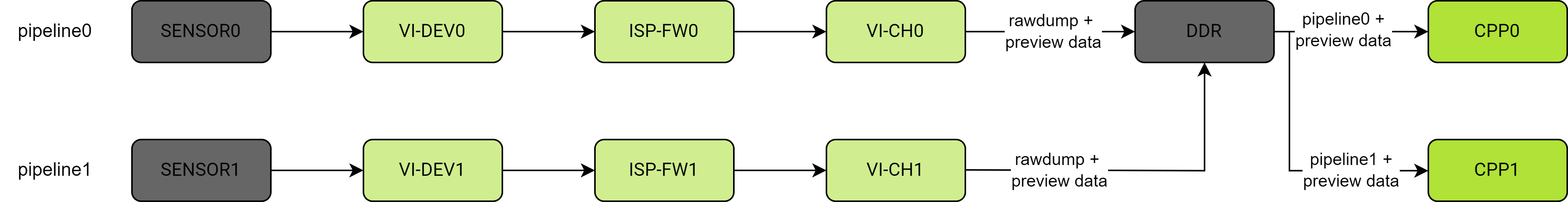
Except that the sensor data comes from two different physical devices, the software processing for both pipelines is exactly the same. That is, Sensor, ISP, VI, and CPP are all configured in duplicate according to the pipeline.
For the first pipeline:
- ISP uses firmware0
- CPP uses pipeline0
- VI uses DEV0 and its associated channels
For the second pipeline:
- ISP uses firmware1
- CPP uses pipeline1
- VI uses DEV1 and its associated channels
Case 3: dual_pipeline_capture_test
In this case, ISP pipeline0 operates in online mode, while ISP pipeline1 operates in offline mode. The rawdump result from ISP pipeline0 serves as the input data for ISP pipeline1. After executing the ASR_ISP_TriggerRawCapture operation, the capture function is realized. The data flow is shown below:
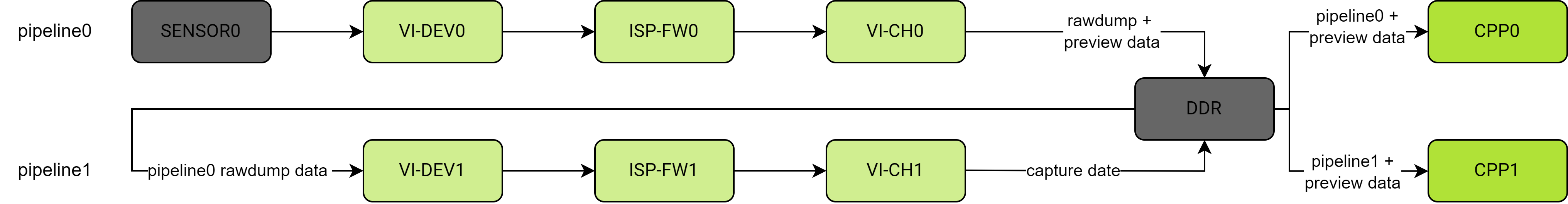
Compared to the previous two cases, note that the pipeline1 workflow is slightly different.
-
The VI module of pipeline1 uses DEV1’s bayerRead channel to read pipeline0’s rawdump results from DDR, and uses the physical channel to output capture results to DDR, while pipeline1’s rawdump channel is inactive.
-
Accordingly, the callback handling of both pipelines changes as follows:
- vi_buffer_callback: VI PHYSICAL channel buffer callback for pipeline0 and pipeline1. Similar to the first two cases, mainly responsible for passing output buffers to their respective CPP modules as input (implemented via
cpp_post_buffer). - isp_buffer_callback: ISP frameInfo callback for pipeline0. Same as the first two cases.
- vi_rawdump_buffer_callback: Rawdump callback for pipeline0. In addition to usual operations such as storing rawdump images, it also needs to notify pipeline1 of the rawdump results so that its bayerRead channel can read the rawdump data and trigger ISP to execute the capture command.
- cpp_buffer_callback: CPP buffer callback for both pipeline0 and pipeline1. Similar to the first two cases.
- vi_buffer_callback: VI PHYSICAL channel buffer callback for pipeline0 and pipeline1. Similar to the first two cases, mainly responsible for passing output buffers to their respective CPP modules as input (implemented via
Executable Applications
The k1x-cam test suite mainly includes the following test programs:
- cam-test: Used for testing and verification of single pipeline, dual pipeline, single raw pipeline, single CPP processing, etc.
- cam_sensors_test: Used for debugging and verifying the simple sensor workflow: detect → init → stream on.
cam-test
Some Basic Usage
Usage example: cam-test <file.json>

// Single pipeline online test: imx135 (4208x3120@30fps raw10 4lane) → ISP -> DDR (1080p@30fps) -> CPP
Command: cam-test demo/cfgs/0/camtest_sensor0_mode0.json

// Single pipeline online test: imx135 (4208x2416@30fps raw10 4lane) → ISP -> DDR (1080p@30fps) -> CPP
Command: cam-test demo/cfgs/0/camtest_sensor0_mode1.json

// Single pipeline online test: imx135 (2104x1560@30fps raw10 4lane) → ISP -> DDR (1080p@30fps) -> CPP
Command: cam-test demo/cfgs/0/camtest_sensor0_mode2.json

// Single pipeline online test: imx135 (2104x1560@30fps raw10 4lane) → ISP -> DDR (1080p@30fps) -> CPP
Command: cam-test demo/cfgs/0/camtest_sensor0_mode2.json

// Dual pipeline capture test: imx135 (2104x1560@30fps raw10 4lane) → ISP -> DDR (1080p@30fps) -> CPP
Command: cam-test demo/cfgs/2/camtest_sensor0_mode0.json

// Only raw dump pipeline test: imx135 (4208x3120@30fps raw10 4lane) → ISP (VI) -> DDR
Command: cam-test demo/cfgs/3/camtest_sensor0_mode0.json

// Only ISP online pipeline test: imx135 → ISP -> DDR (NV12)
Command: cam-test demo/cfgs/4/camtest_sensor0_mode0_nv12.json

// Only ISP online pipeline test: imx135 → ISP -> DDR (p010)
Command: cam-test demo/cfgs/4/camtest_sensor0_mode0_p010.json

// Only ISP online pipeline test: imx135 → ISP -> DDR (p210)
Command: cam-test demo/cfgs/4/camtest_sensor0_mode0_p210.json

// Only ISP online pipeline test: imx135 → ISP -> DDR (rgb565)
Command: cam-test demo/cfgs/4/camtest_sensor0_mode0_rgb565.json

// Only ISP online pipeline test: imx135 → ISP -> DDR (rgb888)
Command: cam-test demo/cfgs/4/camtest_sensor0_mode0_rgb888.json

// Only ISP online pipeline test: imx135 → ISP -> DDR (y210)
Command: cam-test demo/cfgs/4/camtest_sensor0_mode0_y210.json

// Dual pipeline online test: imx135 + gc2375h → ISP -> DDR -> CPP
Command: cam-test demo/cfgs/1/camtest_main_aux.json
JSON Parameter Description, explained using camtest_main_aux.json as an example:
{
    "tuning_server_enable":1, // Used to enable ISP tuning service, effective in only ISP online, single pipeline online, and dual pipeline online tests
    "show_fps":1,    //// Calculate the average frame rate from frames 0 to 120
    "auto_run": 1,   //// Automated testing without user interaction, disabled by default
    "cpp_node": [    //CPP module
            {
                    "name": "cpp0",    //cpp group0
                    "enable": 1,
                    "format":"NV12",
                    "src_from_file": 0,    //If both ISP and CPP are enabled, the input to CPP comes from the output of ISP.
                    "src_path":"/tmp/cpp_case_in_data/1920x1080/",
                    "size_width":1920,
                    "size_height":1080,
            },
            {
                    "name": "cpp1",    //cpp group1
                    "enable": 1,
                    "format":"NV12",
                    "src_from_file": 0,    //
                    "src_path":"/vendor/etc/camera/",
                    "size_width":1920,
                    "size_height":1080,
            },
        ],
    "isp_node":[    //ISP Module: One ISP can accept two video stream inputs.
            {
                    "name": "isp0",    //ISP0 works in online mode, outputting 1080p@30fps NV12.
                    "enable": 1,
                    "work_mode":"online",
                    "format":"NV12",
                    "out_width":1920,
                    "out_height":1080,
                    "sensor_name":"imx135_asr",    //imx135 corresponds to /dev/cam_sensor0, operating in mode 0.
                    "sensor_id" : 0,
                    "sensor_work_mode":0,
                    "fps":30,
                    "src_file":"/tmp/1920x1080_raw12_long_packed.vrf",    //Not effective (used in other modes)
                    "bit_depth": 12,    //Not effective
                    "in_width":1920,    //Not effective
                    "in_height":1080,    //Not effective
            },
            {
                    "name": "isp1",    //isp1在线模式工作,输出1600x1200@30fps NV12
                    "enable": 1,
                    "work_mode":"online",
                    "format":"NV12",
                    "out_width":1600,
                    "out_height":1200,
                    "src_file":"/tmp/1920x1080_raw12_long_packed.vrf",    //不生效
                    "bit_depth": 12,    //Not effective
                    "in_width":1920,    //Not effective
                    "in_height":1080,    //Not effective
                    "sensor_name":"gc2375h_asr",    //gc2375h corresponds to /dev/cam_sensor1, operating in mode 0
                    "sensor_id" : 1,
                    "sensor_work_mode":0,
                    "fps":30,
            },
    ]
}
Check Image Output Status
If the JSON configuration file does not enable auto_run, the user needs to interactively input commands to perform the test. Below are common interaction commands (using camtest_sensor0_mode0.json as an example):
~ # cam-test camtest_sensor0_mode0.json
....
...
s    // Input 's' and press Enter to start the pipeline streaming

...
...    // After some time, you can observe FPS information printed in the log, indicating image data is being received, e.g.,
// “I: cpp_client_receive_mctf_buffers(1833): "CPP0: frameid 342, fps 16.9"”

d    // Input 'd' and press Enter to dump one frame of CPP processed NV12 data (CPP input/output supports NV12 only)

...
...
r    // Input 'r' and press Enter to dump one frame of raw unprocessed data; this RAW data header contains custom data and needs to be viewed using AsrVRFViewer.exe tool

...
...
c    // Input 'c' and press Enter to stop the pipeline streaming

...
...
q    // Input 'q' and press Enter to quit the application
Notes:
- Interactive commands: The actual supported interactive commands depend on the test program code.
- JSON parameters: The detailed functions of JSON parameters can be understood by analyzing the specific application scenarios in
config.c,online_pipeline_test.c, ormain.c.
Practical Logs (For Reference Only)
Kernel Camera-Related Startup Logs
......

[    3.084917] d420a000.csiphy begin to probe
[    3.089254] d420a000.csiphy probed
[    3.089375] d420a800.csiphy begin to probe
[    3.097208] d420a800.csiphy probed
[    3.097322] d4206000.csiphy begin to probe
[    3.105140] d4206000.csiphy probed
[    3.116857] d420a000.ccic begin to probe
[    3.124589] k1xccic d420a000.ccic: ipe irq: 21
[    3.129299] d420a000.ccic probed
[    3.148853] d420a800.ccic begin to probe
[    3.156341] k1xccic d420a800.ccic: ipe irq: 22
[    3.161199] d420a800.ccic probed
[    3.180854] d4206000.ccic begin to probe
[    3.188371] k1xccic d4206000.ccic: ipe irq: 23
[    3.193052] d4206000.ccic probed
[    3.255478] acquire ccic0 ctrl dev succeed
[    3.263109] acquire ccic1 ctrl dev succeed
[    3.267377] acquire ccic2 ctrl dev succeed

......

[    4.573603] cam_sensor soc:cam_sensor@1: supply af_2v8 not found, using dummy regulator
[    4.582230] cam_sensor soc:cam_sensor@1: supply dvdd_1v2 not found, using dummy regulator
[    4.591115] cam_sensor soc:cam_sensor@2: supply af_2v8 not found, using dummy regulator
After a normal startup, you can check the registered device nodes:
Character Device Nodes
Sensors (up to 3 possible)
~ # ls /dev/cam_sensor*
/dev/cam_sensor0  /dev/cam_sensor1  /dev/cam_sensor2
ISP (One ISP node corresponds to two pipes)
~ # ls /dev/mars11isp-pipe*
/dev/mars11isp-pipe0  /dev/mars11isp-pipe1
v4l2 related nodes
~ # ./test.sh
Name for /sys/class/video4linux/v4l-subdev0: mars-cpp
Name for /sys/class/video4linux/v4l-subdev1: sensor0
Name for /sys/class/video4linux/v4l-subdev10: dwt0_layer1
Name for /sys/class/video4linux/v4l-subdev11: dwt0_layer2
Name for /sys/class/video4linux/v4l-subdev12: dwt0_layer3
Name for /sys/class/video4linux/v4l-subdev13: dwt0_layer4
Name for /sys/class/video4linux/v4l-subdev14: dwt1_layer1
Name for /sys/class/video4linux/v4l-subdev15: dwt1_layer2
Name for /sys/class/video4linux/v4l-subdev16: dwt1_layer3
Name for /sys/class/video4linux/v4l-subdev17: dwt1_layer4
Name for /sys/class/video4linux/v4l-subdev18: pipe0
Name for /sys/class/video4linux/v4l-subdev19: pipe1
Name for /sys/class/video4linux/v4l-subdev2: sensor1
Name for /sys/class/video4linux/v4l-subdev20: hdr_combine
Name for /sys/class/video4linux/v4l-subdev21: csi0_main
Name for /sys/class/video4linux/v4l-subdev22: csi1_main
Name for /sys/class/video4linux/v4l-subdev23: csi2_main
Name for /sys/class/video4linux/v4l-subdev24: csi0_vcdt
Name for /sys/class/video4linux/v4l-subdev25: csi1_vcdt
Name for /sys/class/video4linux/v4l-subdev26: csi2_vcdt
Name for /sys/class/video4linux/v4l-subdev3: sensor2
Name for /sys/class/video4linux/v4l-subdev4: rawdump0
Name for /sys/class/video4linux/v4l-subdev5: rawdump1
Name for /sys/class/video4linux/v4l-subdev6: offline_channel0
Name for /sys/class/video4linux/v4l-subdev7: offline_channel1
Name for /sys/class/video4linux/v4l-subdev8: formatter0
Name for /sys/class/video4linux/v4l-subdev9: formatter1
~ # cat test.sh
#!/bin/sh

for directory in /sys/class/video4linux/v4l-subdev*; do
    echo -n "Name for $directory: "
    cat "$directory/name"
done
Normal Operation Single Pipeline Online Test Log
By executing the command cat /proc/sys/kernel/printk, you can check the current kernel print level, which is: 4 4 1 7.
The following test log was generated with auto_run set to 1.
If you encounter any log entries containing E: during the execution of the cam-test command, please contact the relevant engineers to verify if it is normal.
root@spacemit-k1-x-deb1-board:~# cam-test /usr/share/camera_json/csi1_camera_auto.json
I: getTestConfig(438): "json size:1141"
I: getCppNodeConfig(31): "cpp node num: 2"
I: getIspNodeConfig(138): "isp node num: 2"
I: getSensorNodeConfig(323): "no sensor_node, use default config"
tuningServerScene: 1
show_fps: 1
auto_run: 1
test_frame: 500                 //Indicates the number of frames to be tested
dump_one_frame: 250             //Indicates which frame number to save
use_v4l: 0
auto_detect: 0
cpp0 enable: 1
cpp0 src_path: /tmp/cpp_case_in_data/1920x1080/
cpp0 size_width: 1920
cpp0 size_height: 1080
cpp1 enable: 0
cpp1 src_path:
cpp1 size_width: 0
cpp1 size_height: 0
isp0 enable: 1
isp0 work_mode: 0
isp0 format: NV12               //Indicates the YUV format output by the ISP
isp0 out_width: 1920            //Indicates the resolution size of the ISP output
isp0 out_height: 1080
isp0 sensor_name: ov16a10_spm   //Indicates the type of the camera
isp0 sensor_id: 0
isp0 sensor_work_mode: 0
isp0 fps: 30
isp0 src_file:
isp0 bit_depth: 0
isp0 in_width: 0
isp0 in_height: 0
isp1 enable: 0
isp1 work_mode: 0
isp1 format:
isp1 out_width: 0
isp1 out_height: 0
isp1 sensor_name:
isp1 sensor_id: 0
isp1 sensor_work_mode: 0
isp1 fps: 0
isp1 src_file:
isp1 bit_depth: 0
isp1 in_width: 0
isp1 in_height: 0
I: single_pipeline_online_test(1420): "test start"
I: ./sensors/sensor/cam_sensor.c(28): "open device /dev/cam_sensor0"
I: ./sensors/sensor/ov16a10_sensor.c(867): "detect sensor0 success"
I: testSensorInit(75): "sensor config info number 1"
I: testSensorInit(77): "sensor_config_info[0].width 3840"
I: testSensorInit(78): "sensor_config_info[0].height 2160"
I: testSensorInit(80): "sensor_config_info[0].bitDepth 10"
I: testSensorInit(82): "sensor_config_info[0].fps 30.000000"
I: testSensorInit(83): "sensor_config_info[0].image_mode 0"
I: testSensorInit(85): "sensor_config_info[0].lane_num 4"
I: testSensorInit(87): "sensor_config_info[0].work_mode 0"
I: ./sensors/sensor/cam_sensor.c(28): "open device /dev/cam_sensor0"
I: VI_ConfigDev(341): "map viDev(0) workMode(0) bindSensorIdx0(0) bindSensorIdx1(0) to topology:online_offline"
I: VI_ConfigDev(344): "VI switch to topology:online_offline"
I: VI_HAL_SmartSwitchTopologyWithoutApply(2053): "switch topology to online_offline"
I: SetupTopologyPipelineLinks(1402): "enable link(sensor0==>csi0_main)"
I: SetupTopologyPipelineLinks(1402): "enable link(csi0_main==>rawdump0)"
I: SetupTopologyPipelineLinks(1402): "enable link(rawdump0==>aout12)"
I: SetupTopologyPipelineLinks(1402): "enable link(csi0_main==>pipe0)"
I: SetupTopologyPipelineLinks(1402): "enable link(pipe0==>formatter0)"
I: SetupTopologyPipelineLinks(1402): "enable link(formatter0==>aout0)"
I: SetupTopologyPipelineLinks(1402): "enable link(formatter0==>dwt0_layer1)"
I: SetupTopologyPipelineLinks(1402): "enable link(formatter0==>dwt0_layer2)"
I: SetupTopologyPipelineLinks(1402): "enable link(formatter0==>dwt0_layer3)"
I: SetupTopologyPipelineLinks(1402): "enable link(formatter0==>dwt0_layer4)"
I: SetupTopologyPipelineLinks(1402): "enable link(dwt0_layer1==>aout6)"
I: SetupTopologyPipelineLinks(1402): "enable link(dwt0_layer2==>aout7)"
I: SetupTopologyPipelineLinks(1402): "enable link(dwt0_layer3==>aout8)"
I: SetupTopologyPipelineLinks(1402): "enable link(dwt0_layer4==>aout11)"
I: SetupTopologyPipelineLinks(1402): "enable link(ain1==>offline_channel1)"
I: SetupTopologyPipelineLinks(1402): "enable link(offline_channel1==>pipe1)"
I: SetupTopologyPipelineLinks(1402): "enable link(pipe1==>formatter1)"
I: SetupTopologyPipelineLinks(1402): "enable link(formatter1==>aout1)"
I: SetupTopologyPipelineLinks(1402): "enable link(formatter1==>dwt1_layer1)"
I: SetupTopologyPipelineLinks(1402): "enable link(formatter1==>dwt1_layer2)"
I: SetupTopologyPipelineLinks(1402): "enable link(formatter1==>dwt1_layer3)"
I: SetupTopologyPipelineLinks(1402): "enable link(formatter1==>dwt1_layer4)"
I: SetupTopologyPipelineLinks(1402): "enable link(dwt1_layer1==>aout2)"
I: SetupTopologyPipelineLinks(1402): "enable link(dwt1_layer2==>aout3)"
I: SetupTopologyPipelineLinks(1402): "enable link(dwt1_layer3==>aout4)"
I: SetupTopologyPipelineLinks(1402): "enable link(dwt1_layer4==>aout5)"
I: VI_ConfigDev(361): "map viDev(0) workMode(0) to pipe:pipe0"
I: VI_ConfigDev(362): "setup pipe(pipe0) input(mcode:12557 3840x2160)"
I: VI_ConfigDev(372): "apply pipe(pipe0) input"
I: ApplyTopologyPipelineInput(1701): "mipi_lane_num:4"
I: VI_ConfigDev(379): "apply pipe(pipe0)"
I: VI_OpenChnFds(506): "open video6"
I: VI_OpenChnFds(506): "open video12"
I: VI_OpenChnFds(506): "open video13"
I: VI_OpenChnFds(506): "open video14"
I: VI_OpenChnFds(506): "open video17"
I: VI_ConfigChn(562): "VI_ConfigChn set fmt(fourcc:0x3231564e 1920x1080 planes:2) for viChn(0) viChnData(0)"
I: VI_ConfigChn(562): "VI_ConfigChn set fmt(fourcc:0x31313044 960x540 planes:2) for viChn(0) viChnData(1)"
I: VI_ConfigChn(562): "VI_ConfigChn set fmt(fourcc:0x32313044 480x270 planes:2) for viChn(0) viChnData(2)"
I: VI_ConfigChn(562): "VI_ConfigChn set fmt(fourcc:0x33313044 240x135 planes:2) for viChn(0) viChnData(3)"
I: VI_ConfigChn(562): "VI_ConfigChn set fmt(fourcc:0x34313044 120x68 planes:2) for viChn(0) viChnData(4)"
I: CAM_ISP_FwCreate(23): "create isp firmware(version=10326)!"
open /dev/ion failed!
Using DMA-BUF heap named: system
I: CAM_ISP_FWGetStatsSize(48): "all stat size(ae:3864,awb:3456,ltm:6144,af:1300!"
Using DMA-BUF heap named: linux,cma
I: CAM_ISP_FwCreate(23): "create isp firmware(version=10326)!"
I: _ISP_PIPELINE_ConfigFwFromSensor(199): "isp pipeline0 use sensor scene0 setting."
I: CAM_ISP_SensorGetExpoTimeByFps(412): "get fps(25.000000) exposure time from sensor return exp:40014!"
I: CAM_ISP_SensorSetFps(383): "set fps(30.000000) to sensor success!"
I: _ISP_PIPELINE_LoadFwSettingFile(495): "no isp setting file, use settings from user or sensor!"
I: CAM_ISP_DRV_OpenDev(31): "open /dev/mars11isp-pipe0 success, fd=59!"
I: CAM_ISP_3A_InitAeParams(92): "isp use init ae from sensor default exp=33332,again=256,tgain=256,snsdgain=4096,!"
I: _ISP_PIPELINE_InitChannel(633): "no af motor callback for isp init on pipeline0!"
I: CAM_ISP_FwGetAeProcessMode(789): "isp fw ae process at eof with 1 frame!"
I: CAM_ISP_SensorGetExpoTimeByFps(412): "get fps(25.000000) exposure time from sensor return exp:40014!"
I: _ISP_PIPELINE_LoadFwSettingFile(495): "no isp setting file, use settings from user or sensor!"
I: CAM_ISP_DRV_OpenDev(31): "open /dev/mars11isp-pipe0 success, fd=60!"
I: CAM_ISP_SensorUpdateInitAeInfo(125): "isp update sensor init ae exp=20000,again=426,snsdgain=4096,sensor default is (33332-256-4096)!"
I: _ISP_PIPELINE_SetCaptureSliceWidth(1758): "set isp slice width(1728), pad(36), in_w=3840, sns_line_time=13.000000us"
I: cpp_fw_inst_create(429): "Firmware Version: 9333"
I: subdev_node_find_by_name(52): "mars-cpp device node found: /dev/v4l-subdev0"
I: cpp_hardware_create(219): "Hardware Version: 0x00020001"
I: cam_cpp_create_grp(440): "CPP0: cam_cpp_create_grp: X"
I: cpp_init(28): "cpp attr.mode is 0\n"
I: cam_cpp_set_grp_attr(721): "CPP0: cam_cpp_set_grp_attr: 1920x1080, format 1, workmode 0"
I: cam_cpp_set_callback(623): "CPP0: cam_cpp_set_callback: X"
I: buffer_pool_continous_alloc(346): "pool(vi channel0 out buffer) buffer_size=4421120 buffer_count=4 block_size=0\n"
I: buffer_pool_continous_alloc(346): "pool(cpp channel0 out buffer) buffer_size=4421120 buffer_count=4 block_size=0\n"
I: buffer_pool_continous_alloc(346): "pool(vi rawdump channel0 out buffer) buffer_size=11059200 buffer_count=1 block_size=0\n"
I: cam_cpp_load_settingfile(746): "CPP0: cam_cpp_load_settingfile: /usr/share/camera_json/sensor_rear_primary_cpp_preview_setting.data X"
I: cpp_load_fw_settingfile(103): "cpp: load setting file OK\n"
open /dev/ion failed!
Using DMA-BUF heap named: linux,cma
I: cam_cpp_start_grp(502): "CPP0: cam_cpp_start_grp 1920x1080, mctf"
I: VI_EnableDev(467): "start pipe(pipe0)"
I: VI_OpenChnFds(506): "open video6"
I: VI_OpenChnFds(506): "open video12"
I: VI_OpenChnFds(506): "open video13"
I: VI_OpenChnFds(506): "open video14"
I: VI_OpenChnFds(506): "open video17"
I: VI_ConfigChn(562): "VI_ConfigChn set fmt(fourcc:0x3231564e 1920x1080 planes:2) for viChn(0) viChnData(0)"
I: VI_ConfigChn(562): "VI_ConfigChn set fmt(fourcc:0x31313044 960x540 planes:2) for viChn(0) viChnData(1)"
I: VI_ConfigChn(562): "VI_ConfigChn set fmt(fourcc:0x32313044 480x270 planes:2) for viChn(0) viChnData(2)"
I: VI_ConfigChn(562): "VI_ConfigChn set fmt(fourcc:0x33313044 240x135 planes:2) for viChn(0) viChnData(3)"
I: VI_ConfigChn(562): "VI_ConfigChn set fmt(fourcc:0x34313044 120x68 planes:2) for viChn(0) viChnData(4)"
I: VI_NormalCaptureLoop(797): "VI_NormalCaptureLoop chnDataTypeCnt=5\n"
I: VI_OpenChnFds(506): "open video18"
I: VI_ConfigChn(562): "VI_ConfigChn set fmt(fourcc:0x41575270 3840x2160 planes:1) for viChn(2) viChnData(0)"
I: VI_OpenChnFds(506): "open video18"
I: VI_ConfigChn(562): "VI_ConfigChn set fmt(fourcc:0x41575270 3840x2160 planes:1) for viChn(2) viChnData(0)"
I: VI_NormalCaptureLoop(797): "VI_NormalCaptureLoop chnDataTypeCnt=1\n"
I: single_pipeline_online_test(1504): "sensor stream on"

//Frame rate output after stream start, and log of saved frame data
I: cpp_client_receive_mctf_buffers(1833): "CPP0: frameid 1, fps 0.0"
I: vi_buffer_callback(508): "chn0 preview fps: 29.961245"
I: vi_buffer_callback(499): "dump one raw frame"
I: image_buffer_save(204): "save img fileName /tmp/cpp0_output_1920x1080_s1920.nv12"
I: vi_rawdump_buffer_callback(904): "VI chn 2 rawdump buffer frameId 252, buffer 0x3f96be0000, closeDown: 0"
I: raw_buffer_save(258): "save raw img fileName /tmp/raw_output0_3840x2160.raw"
I: cpp_client_receive_mctf_buffers(1833): "CPP0: frameid 301, fps 29.9"

I: VI_DisableDev(487): "stop pipe(pipe0)"
I: _ISP_PIPELINE_DeinitThreads(1672): "start thread exit"
I: _ISP_PIPELINE_DeinitThreads(1676): "end thread exit"
I: _ISP_PIPELINE_DeinitThreads(1680): "af thread exit"
I: _ISP_PIPELINE_DeinitThreads(1684): "capture thread exit"
I: cpp_client_fsm_fn_working(237): "wait for flush, event ident 0x00000000"
I: cpp_client_fsm_fn_working(243): "flush complete"
I: cam_cpp_stop_grp(527): "CPP0: cam_cpp_stop_grp X"
I: single_pipeline_online_test(1513): "sensor stream off"
I: VI_HAL_SmartSwitchTopologyWithoutApply(2069): "detach current topology(online_offline)"
I: SetupTopologyPipelineLinks(1409): "disable link(sensor0==>csi0_main)"
I: SetupTopologyPipelineLinks(1409): "disable link(csi0_main==>rawdump0)"
I: SetupTopologyPipelineLinks(1409): "disable link(rawdump0==>aout12)"
I: SetupTopologyPipelineLinks(1409): "disable link(csi0_main==>pipe0)"
I: SetupTopologyPipelineLinks(1409): "disable link(pipe0==>formatter0)"
I: SetupTopologyPipelineLinks(1409): "disable link(formatter0==>aout0)"
I: SetupTopologyPipelineLinks(1409): "disable link(formatter0==>dwt0_layer1)"
I: SetupTopologyPipelineLinks(1409): "disable link(formatter0==>dwt0_layer2)"
I: SetupTopologyPipelineLinks(1409): "disable link(formatter0==>dwt0_layer3)"
I: SetupTopologyPipelineLinks(1409): "disable link(formatter0==>dwt0_layer4)"
I: SetupTopologyPipelineLinks(1409): "disable link(dwt0_layer1==>aout6)"
I: SetupTopologyPipelineLinks(1409): "disable link(dwt0_layer2==>aout7)"
I: SetupTopologyPipelineLinks(1409): "disable link(dwt0_layer3==>aout8)"
I: SetupTopologyPipelineLinks(1409): "disable link(dwt0_layer4==>aout11)"
I: SetupTopologyPipelineLinks(1409): "disable link(ain1==>offline_channel1)"
I: SetupTopologyPipelineLinks(1409): "disable link(offline_channel1==>pipe1)"
I: SetupTopologyPipelineLinks(1409): "disable link(pipe1==>formatter1)"
I: SetupTopologyPipelineLinks(1409): "disable link(formatter1==>aout1)"
I: SetupTopologyPipelineLinks(1409): "disable link(formatter1==>dwt1_layer1)"
I: SetupTopologyPipelineLinks(1409): "disable link(formatter1==>dwt1_layer2)"
I: SetupTopologyPipelineLinks(1409): "disable link(formatter1==>dwt1_layer3)"
I: SetupTopologyPipelineLinks(1409): "disable link(formatter1==>dwt1_layer4)"
I: SetupTopologyPipelineLinks(1409): "disable link(dwt1_layer1==>aout2)"
I: SetupTopologyPipelineLinks(1409): "disable link(dwt1_layer2==>aout3)"
I: SetupTopologyPipelineLinks(1409): "disable link(dwt1_layer3==>aout4)"
I: SetupTopologyPipelineLinks(1409): "disable link(dwt1_layer4==>aout5)"
I: cam_cpp_destroy_grp(478): "CPP0: cam_cpp_destroy_grp: X"
I: single_pipeline_online_test(1577): "test end"