I2C
I2C Functionality and Usage Guide.
Overview
The I2C bus is a two-wire serial communication protocol used for connecting microcontrollers and their peripheral devices. It is commonly used for master-slave communication between a main controller and its peripherals, suitable for small data volumes and short transmission distances. Each device has its own unique address, and I2C operates in half-duplex mode, allowing only one master to communicate at any given time.
Functional Description
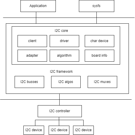
As shown in the figure, the I2C architecture in Linux is divided into three layers:
- User Space: All applications using I2C devices
- Kernel: The drivers
- Hardware: The actual physical devices, including the I2C controller and I2C peripherals.
In the Linux kernel, the I2C driver mainly implements the following logically:
- The I2C framework provides a method for accessing I2C slave devices. Since these slave devices are controlled by the I2C controller, this is primarily implemented by the I2C controller driver.
- Inside the I2C framework, there are four modules: I2C core, I2C busses, I2C algos, and I2C muxes.
- The I2C core uses two sub-modules, I2C adapter and I2C algorithm, to abstract the functionality of the I2C controller.
- I2C busses is a collection of various I2C controller drivers, located in the drivers/i2c/busses/ directory, such as
i2c-k1.c. - I2C algos includes some general I2C algorithms. The so-called algorithm refers to the communication method of the I2C protocol, used to implement I2C read/write instructions.
Source Code Structure
The controller driver code is located in the drivers/i2c/ directory:
drivers/i2c/
|-- i2c-core-of.c       #I2C subsystem core file, providing relevant interface
|-- i2c-boardinfo.c
|-- i2c-core-base.c
|-- i2c-core-slave.c
|-- i2c-core-smbus.c
|-- i2c-dev.c           #I2C subsystem device-related file, used for registering
|-- busses/i2c-k1x.c    #I2C controller driver code for the k1 platform
Key Features
Features
| Feature | Description |
|---|---|
| Support for 9 I2C groups | Supports 9 I2C interfaces |
| Support for DMA | Supports DMA data transfer in host mode |
| Support for 100k / 400k / 1.5M speed modes | Supports three speed modes, configurable via dts |
| Support for bus arbitration | Supports bus arbitration in multi-master mode |
Configuration
It mainly includes driver enablement configuration and dts configuration.
CONFIG Configuration
- CONFIG_I2C and CONFIG_I2C_SPACEMIT_K1X: By default, these options are set to
Y.
Device Drivers
        I2C support
                I2C support (I2C [=y])
                        I2C Hardware Bus support
                               Spacemit k1x I2C adapter (I2C_SPACEMIT_K1X [=y])
- CONFIG_I2C_SLAVE enables I2C slave mode support, for example:
Device Drivers
        I2C support
                I2C support (I2C [=y])
                        I2C slave support (I2C_SLAVE [=y])
- CONFIG_I2C_CHARDEV enables the I2C character device interface.
Device Drivers
        I2C support
                I2C support (I2C [=y])
                        I2C device interface (I2C_CHARDEV [=y])
DTS Configuration
The I2C bus configuration is as follows:
| Configuration | Description |
|---|---|
spacemit,i2c-fast-mode | 4400K speed mode |
spacemit,i2c-high-mode | 1.5M speed mode |
spacemit,dma-disable | Disable DMA transfer |
The default bus speed is 100K. To switch speed modes, simply add the corresponding configuration in the dts.
For example, to switch to fast mode, configure as follows:
i2c6: i2c@d4018800 {
        spacemit,i2c-fast-mode;
};
Taking i2c6 as an example, to disable DMA transfer, configure in k1-x.dtsi as follows:
i2c6: i2c@d4018800 {
        spacemit,dma-disable;
};
The spacemit,dma-disable configuration indicates that DMA transfer is not used. To enable DMA transfer, simply remove this configuration from the dts.
pinctrl
Check the development board schematic to find the pin group used by the I2C controller.
Taking i2c6 as an example, assuming that the schematic uses gpio56/57 as SCL/SDA respectively, and the configuration can use the pinctrl_i2c6_2 group already defined in k1-x_pinctrl.dtsi, then the solution dts configuration is as follows:
&i2c6 {
        pinctrl-names = "default";
        pinctrl-0 = <&pinctrl_i2c6_2>;
};
I2C Device Configuration
Taking the touchscreen device as an example, let's analyze how to configure the DTS for an I2C device.
Device Type
Confirm the device type and the driver it uses.
Select the compatible configuration for the touchscreen device as goodix,gt9xx.
Device Address
Confirm “the I2C communication address - 7-bit”.
Check the schematic to get the address of the touchscreen device, which is 0x5d, and configure it as follows:
gt9xx@5d {
        compatible = "goodix,gt9xx";
        reg = <0x5d>;
}
Communication Frequency
Confirm the communication frequency of the device.
The touchscreen supports a communication frequency of 100K. Since it is connected to I2C bus6, remove the spacemit,i2c-fast-mode and spacemit,i2c-high-mode configurations to use the default rate of 100K.
Device Control Signals
Check the schematic of the solution to find the control signals used by the device.
The reset and IRQ signals for the touchscreen are gpio 114 and 58, respectively. irq-flags should be configured according to the desired interrupt trigger method. For example, 2 indicates falling edge trigger. The configuration is as follows:
gt9xx@5d {
        reset-gpios = <&gpio 114 GPIO_ACTIVE_HIGH>;
        irq-gpios = <&gpio 58 GPIO_ACTIVE_HIGH>;
        irq-flags = <2>;
};
Device DTS
The touchscreen device address is 0x5d, with gpio 114/58 as the reset/IRQ signals, respectively. The interrupt is triggered on the falling edge, and the communication frequency is 100K. Configure the touchscreen parameters accordingly.
The device dts configuration is as follows:
gt9xx@5d {
                compatible = "goodix,gt9xx";
                reg = <0x5d>;
                reset-gpios = <&gpio 114 GPIO_ACTIVE_HIGH>;
                irq-gpios = <&gpio 58 GPIO_ACTIVE_HIGH>;
                irq-flags = <2>;
                touchscreen-max-id = <11>;
                touchscreen-size-x = <1200>;
                touchscreen-size-y = <1920>;
                touchscreen-max-w = <512>;
                touchscreen-max-p = <512>;
 };
DTS Example
Combining the above information, the solution DTS configuration for i2c6 connected to an I2C touchscreen device is as follows:
&i2c6 {
        pinctrl-names = "default";
        pinctrl-0 = <&pinctrl_i2c6_2>;
        status = "okay";

        gt9xx@5d {
                compatible = "goodix,gt9xx";
                reg = <0x5d>;
                reset-gpios = <&gpio 114 GPIO_ACTIVE_HIGH>;
                irq-gpios = <&gpio 58 GPIO_ACTIVE_HIGH>;
                irq-flags = <2>;
                touchscreen-max-id = <11>;
                touchscreen-size-x = <1200>;
                touchscreen-size-y = <1920>;
                touchscreen-max-w = <512>;
                touchscreen-max-p = <512>;
      };
};
Interface
API
Kernel Space: I2C read/write communication uses the standard Linux interfaces. Please refer to the Documentation/i2c/writing-clients.rst document in the kernel directory for detailed instructions on sending and receiving.
User Space: From user space, you can access all devices on the bus through the /dev/i2c-%d node. The demo example provides a simple way to read from and write to I2C devices. For more information, refer to the Documentation/i2c/dev-interface.rst document.
Demo Example
#include <stdio.h>
#include <stdlib.h>
#include <stdint.h>
#include <unistd.h>
#include <sys/ioctl.h>
#include <fcntl.h>
#include <linux/i2c-dev.h>
#define I2C_DEV_FILE "/dev/i2c-1" // The I2C device file path is typically /dev/i2c-1.
#define DEVICE_ADDR 0x68 // The I2C device address, for example, 0x68 (modify according to the actual device).
// Data to the I2C device
int write_to_i2c(int file, uint8_t reg, uint8_t value) {
uint8_t buffer[2];
buffer[0] = reg; // Register address
buffer[1] = value; // Value to write
if (write(file, buffer, 2) != 2) {
perror("I2C write failed");
return -1;
}
return 0;
}
// Read data from the I2C device
int read_from_i2c(int file, uint8_t reg, uint8_t *data, size_t len) {
if (write(file, ®, 1) != 1) {
perror("I2C write register failed");
return -1;
}
if (read(file, data, len) != len) {
perror("I2C read failed");
return -1;
}
return 0;
}
int main() {
int file;
uint8_t data[2]; // Used to store the data read
// Open the I2C device file
if ((file = open(I2C_DEV_FILE, O_RDWR)) < 0) {
perror("Failed to open I2C bus");
exit(1);
}
// Set the address of the I2C slave device
if (ioctl(file, I2C_SLAVE, DEVICE_ADDR) < 0) {
perror("Failed to acquire bus access and/or talk to slave");
close(file);
exit(1);
}
if (write_to_i2c(file, 0x6B, 0x00) < 0) {
close(file);
exit(1);
}
printf("Write 0x00 to register 0x6B\n");
if (read_from_i2c(file, 0x75, data, 1) < 0) {
close(file);
exit(1);
}
printf("Read data 0x%02x from register 0x75\n", data[0]);
// Close the I2C device file
close(file);
return 0;
}
Debugging
sysfs
debugfs
Testing Introduction
I2C tools are open-source utilities that can be downloaded and cross-compiled for use. (Download link) After compilation, tools such as i2cdetect, i2cdump, i2cset, and i2cget are generated, which can be used directly from the command line for debugging:
- i2cdetect: Lists all devices on the I2C bus.
- i2cdump: Displays the values of all registers on an I2C device.
- i2cset: Sets the value of a specific register on an I2C device.
- i2cget: Reads the value of a specific register on an I2C device.
FAQ
Q1. I2C Transmission Timeout Issue
The abnormal log is as follows:
[  126.800897] i2c-spacemit-k1x d401d800.i2c: msg completion timeout
[  126.816937] i2c-spacemit-k1x d401d800.i2c: bus reset, send clk: 0
[  126.830458] i2c-spacemit-k1x d401d800.i2c: i2c transfer retry 1, ret -110 mode 0 err 0x0
...
Troubleshooting steps:
- Check the I2C hardware resistors. If there is a slave device on the SDA line that requires a bypass capacitor, it is recommended to replace the SDA pull-up resistor with a 1k resistor.
- Confirm the I2C pinctrl drive capability. Increase the pinctrl drive capability of the corresponding I2C port to
PAD_1V8_DS2.
	pinctrl_i2c1: i2c1_grp {
		pinctrl-single,pins =<
			K1X_PADCONF(GPIO_56, MUX_MODE1, (EDGE_NONE | PULL_UP | PAD_1V8_DS2))	/* i2c1_scl */
			K1X_PADCONF(GPIO_57, MUX_MODE1, (EDGE_NONE | PULL_UP | PAD_1V8_DS2))	/* i2c1_sda */
		>;
	};