SPI
SPI Functionality and Usage Guide.
Overview
SPI (Serial Peripheral Interface) is a serial communication interface between SoC (System on Chip) and peripherals, supporting only x1 (single-line) mode. SPI has two modes: Master and Slave. Typically, one master device controls one or more slave devices for communication. The master device selects a slave device for communication and completes data exchange. The master device is responsible for providing the clock and initiating read/write operations. The K1 SPI currently supports Master mode only.
Function Description
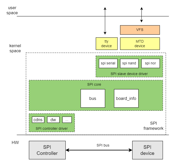
The Linux SPI driver framework consists of three layers: SPI Core, SPI Controller Driver, and SPI Device Driver.
-
The main functions of SPI Core are:
- Manages the registration of the SPI bus and the
spi_masterclass. - Handles the addition and removal of SPI controllers.
- Manages the addition and removal of SPI devices.
- Registers and unregisters SPI device drivers.
- Manages the registration of the SPI bus and the
-
SPI Controller Driver:
- This is the SPI Master controller driver, responsible for operating the SPI Master controller.
-
SPI Device Drive:
- Implements communication with specific SPI peripherals.
Source Code Structure
The controller driver code is located in the drivers/spi directory:
|-- spi-k1x.c # K1 SPI driver
Key Features
| Feature | Description |
|---|---|
| Communication Protocol | Supports SSP/SPI/MicroWire/PSP protocols |
| Communication Frequency | Maximum frequency supported is 52Mbps; Minimum frequency supported is 6.3Kbps |
| Bus Width | x1 (single-line mode) |
| Supported Peripherals | Supports SPI-NOR and SPI-NAND flash memory |
Performance Parameters
-
Communication Frequency The supported communication frequencies are 51.2M / 25.6M / 12.8M / 6.4M / 3.2M / 1.6M / 1M / 200k.
-
Bus Width SPI Bus Width supports x1.
Testing Method
Use an oscilloscope or logic analyzer to measure the SCK (Serial Clock) frequency。
Configuration Introduction
This mainly includes Driver Enable Configuration and DTS Configuration.
CONFIG Configuration
CONFIG_SPI: Provides support for the SPI bus protocol. By default, this option is set to Y.
Device Drivers
        SPI support (SPI [=y])
CONFIG_SPI_K1X: Provides support for the K1 SPI controller driver. By default, this option is also set to Y.
Device Drivers
        SPI support (SPI [=y])
                K1X SPI Controller (SPI_K1X [=y])
DTS Configuration
pinctrl
Refer to the schematic diagram of the reference design to identify the pin group used by the SPI. For more details on pin configuration, refer to the PINCTRL documentation. For example:
SPI3 can use the pinctrl_ssp3_0 group defined in k1-x_pinctrl.dtsi.
SPI Device Configuration
When configuring an SPI device, you need to confirm the device type and the communication frequency parameters.
-
Device Type Identify the type of device connected to the SPI bus, such as SPI-NOR or SPI-NAND.
-
Communication Frequency Specify the maximum communication rate between the SPI controller and the SPI device.
-
Communication Width QSPI communication width supports x1 mode.
SPI Device DTS Configuration Example: For an SPI NOR device, configure the maximum communication frequency to 26 MHz, with both transmit and receive operations in x1 mode.
&spi3 {
        pinctrl-names = "default";
        pinctrl-0 = <&pinctrl_ssp3_0>;
        k1x,ssp-disable-dma;
        status = "okay";
        k1x,ssp-clock-rate = <25600000>;

        flash@0 {
                compatible = "jedec,spi-nor";
                reg = <0>;
                spi-max-frequency = <25600000>;
                m25p,fast-read;
                broken-flash-reset;
                status = "okay";
        };
};
Interface
API
Device Driver Registration and Unregistration
int __spi_register_driver(struct module *owner, struct spi_driver *sdrv);
void spi_unregister_driver(struct spi_driver *sdrv);
Data Transfer APIs
- Initializing
spi_message
void spi_message_init(struct spi_message *m);
- Add s
spi_transferto the transfer list ofspi_message
void spi_message_add_tail(struct spi_transfer *t, struct spi_message *m);
- Writing Data
int spi_write(struct spi_device *spi, const void *buf, size_t len);
- Reading Data
int spi_read(struct spi_device *spi, void *buf, size_t len);
- Synchronous transfer of
spi_message
int spi_sync(struct spi_device *spi, struct spi_message *message);
Debugging
sysfs
View SPI bus device and driver information in the system.
/sys/bus/spi
|-- devices                 // Devices on the SPI bus
|-- drivers                 // Drivers registered on the SPI bus
|-- drivers_autoprobe
|-- drivers_probe
`-- uevent
debugfs
Used to view information about SPI devices in the system.
/sys/kernel/debug/spi-nor/spi3.0
Testing
SPI NAND/NOR Read/Write Speed Test
-
Enable
CONFIG_MTD_TESTSDevice Drivers
Memory Technology Device (MTD) support (MTD [=y])
MTD tests support (DANGEROUS) (MTD_TESTS [=m]) -
Run the test command
insmod mtd_speedtest.ko dev=0 # 0 indicates the MTD device number for SPI-NAND/NOR