UART
UART Functionality and Usage Guide.
Overview
UART is a universal serial protocol for asynchronous communication. This bus supports bidirectional communication and can achieve full-duplex transmission and reception.
Functional Description
The kernel uses UART to implement the console, and some peripherals, such as Bluetooth, can communicate with the main controller through UART. The K1 platform supports 9 UART devices that can be configured and enabled as needed to connect peripherals.
Source Code Structure
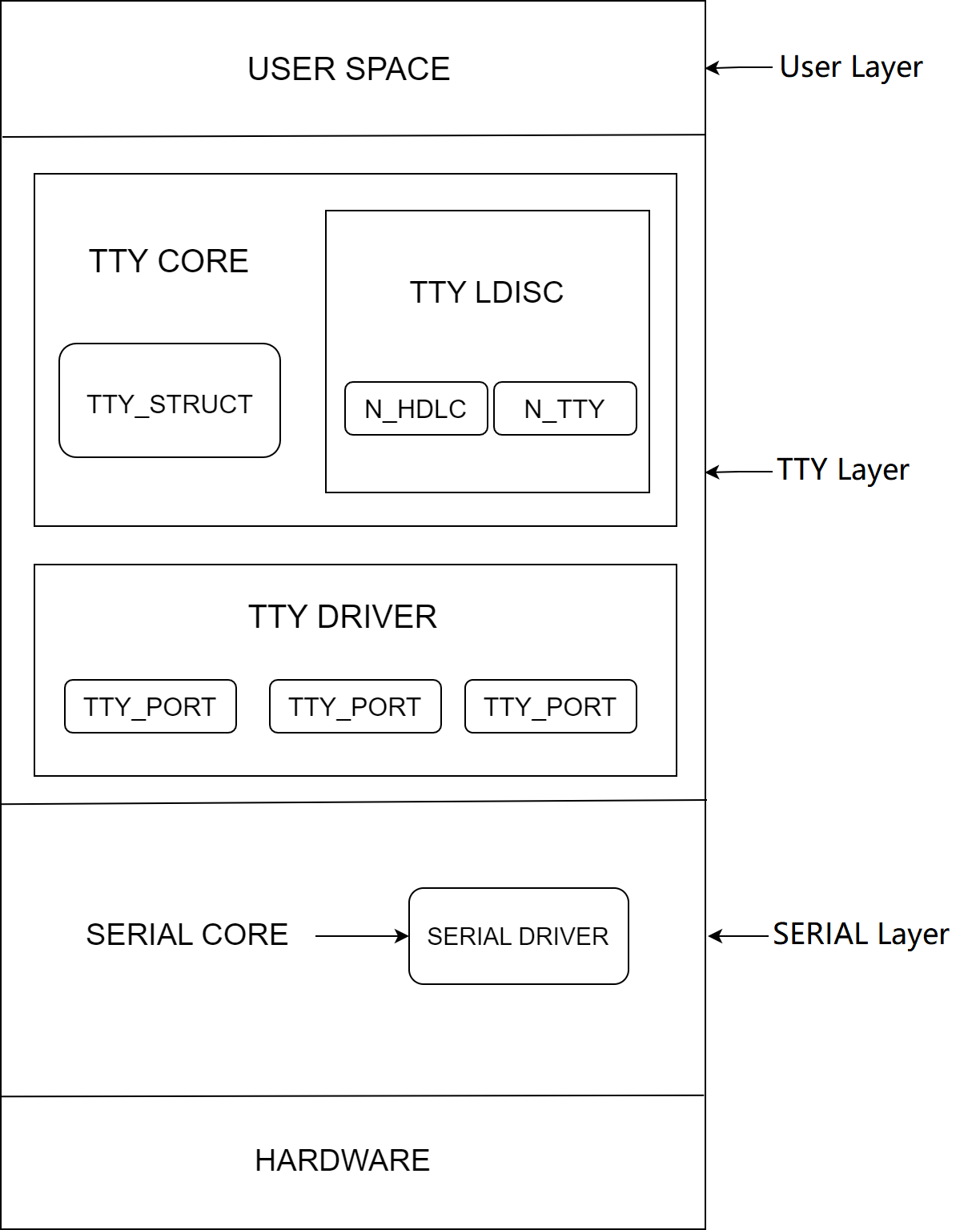
The UART controller driver code is located in the drivers/tty/serial directory:
drivers/tty/serial
|--serial_core.c        #Kernel UART framework interface code
|--pxa_k1x.c        #K1 UART driver
Key Features
Features
- Supports hardware flow control (UART2/UART3)
- Supports DMA transfer mode
- Supports interrupt mode
- Supports RS485/RS232 serial protocols
- Supports 64B RX/TX FIFO
- The K1 platform supports 9 configurable UARTs
Performance Parameters
- Baud rate up to 3M
Configuration
It mainly includes driver enablement configuration and DTS configuration.
CONFIG Configuration
CONFIG_SERIAL_PXA_SPACEMIT_K1X=y
This is the configuration for the K1 UART driver to enable the K1 UART driver
Symbol: SERIAL_PXA_SPACEMIT_K1X [=y]
Device Drivers
    -> Character devices
  -> Serial drivers
   -> PXA serial driver (<choice> [=y])
    -> Spacemit PXA driver suppor (SERIAL_PXA_SPACEMIT_K1X [=y])
DTS Configuration
Since the usage and configuration methods for the 9 UARTs are similar, here we use UART2as an example.
pinctrl
You can refer to the pre-configured UART node settings in the Linux repository arch/riscv/boot/dts/spacemit/k1-x_pinctrl.dtsi as shown below:
 pinctrl_uart2: uart2_grp {
  pinctrl-single,pins =<
   K1X_PADCONF(GPIO_21, MUX_MODE1, (EDGE_NONE | PULL_UP | PAD_1V8_DS2))    /* uart2_txd */
   K1X_PADCONF(GPIO_22, MUX_MODE1, (EDGE_NONE | PULL_UP | PAD_1V8_DS2))    /* uart2_rxd */
   K1X_PADCONF(GPIO_23, MUX_MODE1, (EDGE_NONE | PULL_UP | PAD_1V8_DS2))    /* uart2_cts_n */
   K1X_PADCONF(GPIO_24, MUX_MODE1, (EDGE_NONE | PULL_UP | PAD_1V8_DS2))    /* uart2_rts_n */
  >;
 };
dtsi Configuration Example
In the .dtsi file, the UART controller's base address and clock/reset resources are configured. Typically, no modification is needed.
 uart2: uart@d4017100 {
  compatible = "spacemit,pxa-uart";
  reg = <0x0 0xd4017100 0x0 0x100>;
  interrupt-parent = <&intc>;
  interrupts = <44>;
  clocks = <&ccu CLK_UART2>, <&ccu CLK_SLOW_UART>;
  clock-names = "func", "gate";
  clk-fpga = <14750000>;
  resets = <&reset RESET_UART2>;
  /*dmas = <&pdma0 DMA_UART2_RX 1
    &pdma0 DMA_UART2_TX 1>;
  dma-names = "rx", "tx";*/
  power-domains = <&power K1X_PMU_BUS_PWR_DOMAIN>;
  clk,pm-runtime,no-sleep;
  cpuidle,pm-runtime,sleep;
  interconnects = <&dram_range4>;
  interconnect-names = "dma-mem";
  status = "disabled";
 }
DTS Configuration Example
The complete DTS configuration is shown below:
 &uart2 {
  pinctrl-names = "default";
  pinctrl-0 = <&pinctrl_uart2>;
  status = "okay";
 };
Interface
API
The K1 UART driver implements interfaces for sending data, setting transfer modes, and configuring parity bits, and registers them with the UART framework. Commonly used:
static void serial_pxa_start_tx(struct uart_port *port)
# This interface initiates UART transmission (in interrupt mode).

static void serial_pxa_set_mctrl(struct uart_port *port, unsigned int mctrl)
# This interface sets the UART transmission mode.

static void serial_pxa_set_termios(struct uart_port *port, struct ktermios *termios,
                           const struct ktermios *old)
# This interface sets UART attributes such as stop bits and parity bits.
Testing
UART testing can be completed in loopback mode by connecting the TX signal to the RX signal of the same device.
Program Implementation Logic:
- Take UART3 as an example. After enabling UART3 in the DTS, first check whether
/dev/ttyS2exists. If it does, UART3 has been successfully initialized. - Open the ttyS2 node, then configure its properties such as baud rate, stop bits, and parity.
- Send data: the data will move from the TX FIFO to the RX FIFO through an external loopback. Read the received data from ttyS2 and compare it with the sent data. If they match, the UART functionality is considered normal.