Wi-Fi
Wi-Fi Porting and Usage Guide.
Overview
The K1 platform implements Wi-Fi via external modules supporting PCIe, SDIO, and USB. interfaces.
Function Description
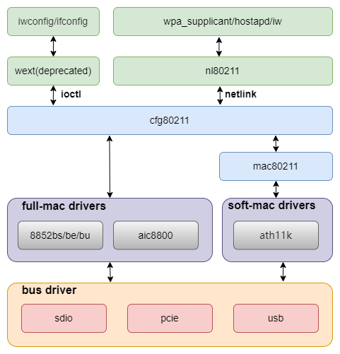
The Wi-Fi architecture is divided into multiple layers, as shown in the figure below:
Source Code Structure
The source code related to Wi-Fi can be divided into three parts:
-
Wi-Fi Driver
Provided by the Wi-Fi vendor, it mainly implements the Wi-Fi functionality.
-
Platform-Related Part
Mainly implements module power supply and enable-related interfaces, which are called by the Wi-Fi driver.
-
Interface Driver
Mainly implements the data transfer interface functions of Wi-Fi, such as PCIe, SDIO, and USB interfaces.
The source code of the Wi-Fi driver is generally placed in the following directory:
drivers/net/wireless
|-- aic8800             # Driver for AIC vendor
|-- realtek             # Driver for Realtek vendor
    |-- rtl8852be       # rtl8852be
    |-- rtl8852bs       # rtl8852bs
|-- wuqi                # Driver for WUQI vendor
Platform-Related Source Code::
drivers/soc/spacemit/spacemit-rf
|-- spacemit-pwrseq.c   # Implementation of common parts for Wi-Fi and Bluetooth
|-- spacemit-wlan.c     # Implementation of Wi-Fi power supply, GPIO, and clock-related interfaces
|-- spacemit-bt.c       # Implementation of BT power supply, GPIO, and clock-related interfaces
Interface-Related Source Code: Refer to the documentation for each interface driver for details.
Key Features
SDIO Interface Support
| Feature | Description |
|---|---|
| Compatible with SDIO v4.10 | Supports 4-bit SDIO 4.10 specification |
| Supports SD 3.0 mode | Supports SDR12/SDR25/DDR50/SDR50/SDR104 modes |
| Supports PIO/DMA | Supports PIO, SDMA, ADMA, ADMA2 transfer modes |
Performance Parameters
| Module Model | TX(Mb/s) | RX(Mb/s) |
|---|---|---|
| rtl8852bs | 460 | 480 |
| aic8800d80 | 410 | 470 |
Testing Method
Prerequisite: Server and client on the same LAN.

# Server
iperf3 -s

# Client
iperf3 -c 192.168.1.xxx -t 72000
Configuration
It mainly includes Driver Enable Configuration and DTS Configuration.
CONFIG Configuration
CONFIG_SPACEMIT_RFKILL: Provides platform-related support for the Wi-Fi module. By default, this option is set to Y
Device Drivers
        SOC (System On Chip) specific Drivers
                Spacemit rfkill driver (SPACEMIT_RFKILL [=y])
DTS Configuration
SDIO pinctrl
Typically, slot2 (for SDIO) maps to pinctrl_mmc2:
pinctrl_mmc2: mmc2_grp {
        pinctrl-single,pins =<
                K1X_PADCONF(GPIO_15, MUX_MODE1, (EDGE_NONE | PULL_UP | PAD_1V8_DS2))	/* mmc2_data3 */
                K1X_PADCONF(GPIO_16, MUX_MODE1, (EDGE_NONE | PULL_UP | PAD_1V8_DS2))	/* mmc2_data2 */
                K1X_PADCONF(GPIO_17, MUX_MODE1, (EDGE_NONE | PULL_UP | PAD_1V8_DS2))	/* mmc2_data1 */
                K1X_PADCONF(GPIO_18, MUX_MODE1, (EDGE_NONE | PULL_UP | PAD_1V8_DS2))	/* mmc2_data0 */
                K1X_PADCONF(GPIO_19, MUX_MODE1, (EDGE_NONE | PULL_UP | PAD_1V8_DS2))	/* mmc2_cmd */
                K1X_PADCONF(GPIO_20, MUX_MODE1, (EDGE_NONE | PULL_UP | PAD_1V8_DS2))	/* mmc2_clk */
        >;
};
For Wi-Fi wake-up support, configure wlan_hostwake to pinctrl mode:
pinctrl_wlan_wakeup: wlan_wakeup_grp {
        pinctrl-single,pins =<
                K1X_PADCONF(GPIO_66, MUX_MODE0, (EDGE_FALL | PULL_DOWN | PAD_3V_DS2))   /* Wi-Fi edge detect */
        >;
};
Power Configuration
SDIO requires two power supplies:
vmmc-supply: Provides power for the card’s functional logic.
vqmmc-supply: Provides power for the card’s I/O. A voltage of 1.8 V is recommended; however, the actual value should be selected based on the SDIO card’s operating mode.
&sdhci1 {
        vmmc-supply = <&dcdc_3>;
        vqmmc-supply = <&ldo_1>;
};
Tuning Configuration
Tuning is required when SDIO operates in high-speed modes. Different hardware versions need to adjust the relevant TX parameters.
SDIO DTS Configuration Example
The complete configuration for the SDIO solution is as follows:
/* SDIO */
&sdhci1 {
        pinctrl-names = "default";
        pinctrl-0 = <&pinctrl_mmc2>;
        bus-width = <4>;
        non-removable;
        vqmmc-supply = <&dcdc_3>;
        no-mmc;
        no-sd;
        keep-power-in-suspend;

        spacemit,sdh-host-caps-disable = <(
                        MMC_CAP_UHS_DDR50 |
                        MMC_CAP_NEEDS_POLL
                        )>;
        spacemit,sdh-quirks = <(
                        SDHCI_QUIRK_BROKEN_CARD_DETECTION |
                        SDHCI_QUIRK_BROKEN_TIMEOUT_VAL
                        )>;
        spacemit,sdh-quirks2 = <(
                        SDHCI_QUIRK2_PRESET_VALUE_BROKEN |
                        SDHCI_QUIRK2_BROKEN_PHY_MODULE
                        )>;
        spacemit,rx_dline_reg = <0x0>;
        spacemit,tx_delaycode = <0x7f>;
        spacemit,rx_tuning_limit = <50>;
        spacemit,sdh-freq = <375000000>;
        status = "okay";
};
The default value of sdio tx_delaycode is 0x7f, but may require tuning based on PCB layout and hardware design.
Platform DTS Configuration
The complete platform configuration is as follows:
rf_pwrseq: rf-pwrseq {
        compatible = "spacemit,rf-pwrseq";
        //vdd-supply = <&ldo_7>;
        //vdd_voltage = <3300000>;
        io-supply = <&dcdc_3>;
        io_voltage = <1800000>;
        pwr-gpios  = <&gpio 67 0>;
        status = "okay";

        wlan_pwrseq: wlan-pwrseq {
                compatible = "spacemit,wlan-pwrseq";
                regon-gpios = <&gpio 116 0>;
                interrupt-parent = <&pinctrl>;
                interrupts = <268>;
                pinctrl-names = "default";
                pinctrl-0 = <&pinctrl_wlan_wakeup>;
        };

        bt_pwrseq: bt-pwrseq {
                compatible = "spacemit,bt-pwrseq";
                reset-gpios     = <&gpio 63 0>;
        };
};
rf_pwrseq configuration:
vdd-supply: The main power supply for the module, configured according to the actual hardware.vdd_voltage: Used to set the voltage for the module's power supply.io-supply: Configures the power supply for the module's IO, based on the actual hardware.io_voltage: Used to set the voltage for the module's IO power supply.pwr-gpios: The main enable pin for the module, pulled high by default when powered on, supports multiple GPIOs.clock: The clock configuration shared by the module.power-on-delay-ms: The delay after the module is powered on, default is 100ms.
wlan_pwrseq configuration:
regon-gpios: The enable pin for the Wi-Fi module, pulled high whenspacemit_wlan_set_power(1)is called.interrupts: The wake-up interrupt pin for the Wi-Fi module, indicating that wake-up is done via pinctrl.power-on-delay-ms: The power-on delay for Wi-Fi, default is 10ms.
bt_pwrseq configuration:
reset-gpios: The reset pin for the Bluetooth module, pulled high when enabling the correspondingrfkillnode for Bluetooth.clock: The clock configuration for Bluetooth.power-on-delay-ms: The power-on delay for Bluetooth, default is 10ms.
Most modules on the market today are combo modules that integrate Wi-Fi and Bluetooth, and their power supply parts are usually shared. It is recommended to configure the shared parts in the rf_pwrseq node and the Wi-Fi-specific parts in the wlan_pwrseq node.
If a single Wi-Fi module is used, only the wlan_pwrseq needs to be configured. There is no need to configure the rf_pwrseq, but the rf_pwrseqnode must be enabled.
When the Wi-Fi power is turned on, the platform will first enable the shared power supply and GPIO states and maintain the corresponding reference counts. When turning off, the platform will only truly shut down the shared power supply and GPIO states after both Wi-Fi and Bluetooth are disabled.
Interface
API
The platform provides interfaces for controlling Wi-Fi power, obtaining interrupts, and scanning the SDIO bus:
-
void spacemit_wlan_set_power(bool on_off);Set the Wi-Fi power0: off1: on.
-
int spacemit_wlan_get_oob_irq(void);Obtain the platform interrupt request (IRQ) number. -
void spacemit_sdio_detect_change(int enable_scan);Scan the SDIO bus.
Debugging
sysfs
The tx_delaycode parameter for SDIO is specified by default in the DTS of the solution.
During debugging, the value can be dynamically modified through the corresponding node in sysfs for verification.
echo 0x7f > /sys/devices/platform/soc/d4280800.sdh
Note: Changes must be applied before loading the Wi-Fi driver to take effect.
debugfs
It is commonly used to query the working status of SDIO, including frequency, bus width, mode, and other information.
cat /sys/kernel/debug/mmc1/ios
clock:          204800000 Hz
actual clock:   187500000 Hz
vdd:            21 (3.3 ~ 3.4 V)
bus mode:       2 (push-pull)
chip select:    0 (don't care)
power mode:     2 (on)
bus width:      2 (4 bits)
timing spec:    6 (sd uhs SDR104)
signal voltage: 1 (1.80 V)
driver type:    0 (driver type B)
Testing
Step 1: Ensure that the wpa_supplicant service is running properly.
wpa_supplicant -iwlan0 -Dnl80211 -c/wpa_supplicant.conf -B
Step 2: Configure wpa_supplicant.conf as follows:
ctrl_interface=/var/run/wpa_supplicant
wowlan_triggers=any
wowlan_triggers is a configuration related to WoW (Wake-on-Wireless), used to support the Wi-Fi wake-up function.
Step 3: Use wpa_cli to interact with the wpa_supplicant service.
If the ctrl_interface path in wpa_supplicant.conf is not the default /var/run/wpa_supplicant, then wpa_cli must be run with the -p option to specify the path.
wpa_cli -iwlan0 -p/var/run/wpa_supplicant
Scan for available wireless networks nearby:
 scan
 scan_results
A normal scan will produce output similar to the following:
bssid / frequency / signal level / flags / ssid
f6:12:b3:d4:65:ef       2462    -37     [WPA2-PSK-CCMP][WPS][ESS][P2P]  wilson
78:85:f4:82:01:3c       2462    -66     [WPA2-PSK-CCMP][WPS][ESS]       HUAWEI-LX45AG_HiLink
02:0e:5e:76:a5:6e       2412    -69     [WPA-PSK-CCMP+TKIP][ESS]        ChinaNet-1mMr
30:8e:7a:2f:64:8c       2437    -69     [WPA-PSK-CCMP+TKIP][WPA2-PSK-CCMP+TKIP][ESS]    K03_1tlftb
dc:16:b2:57:9e:65       2437    -78     [WPA2-PSK-CCMP][ESS]    \x00\x00\x00\x00\x00\x00\x00\x00
dc:16:b2:57:9e:60       2437    -78     [WPA-PSK-CCMP][WPA2-PSK-CCMP][WPS][ESS] TK-ZJB
48:0e:ec:ad:52:4d       2462    -78     [WPA-PSK-CCMP][WPA2-PSK-CCMP][WPS][ESS] TP-LINK_524D
3c:d2:e5:c6:08:9b       2452    -83     [WPA2-PSK-CCMP][ESS]
3e:d2:e5:16:08:9b       2452    -83     [WPA-PSK-CCMP+TKIP][WPA2-PSK-CCMP+TKIP][ESS]    young
80:ea:07:dc:f2:be       2462    -88     [WPA-PSK-CCMP][WPA2-PSK-CCMP][ESS]      HZXF
9a:00:74:84:d1:60       2412    -85     [WPA-PSK-CCMP+TKIP][WPA2-PSK-CCMP+TKIP][ESS]   ChinaNet-ieR7
dc:f8:b9:46:ec:30       2472    -85     [WPA-PSK-CCMP+TKIP][WPA2-PSK-CCMP+TKIP][ESS]   ChinaNet-MiZK
Step 4: Select the desired AP (Access Point) network to connect to.
> add_network
0
> set_network 0 ssid "wilson"
OK
> set_network 0 key_mgmt WPA-PSK
OK
> set_network 0 psk "wilson2001"
OK
> enable_network 0
FAQ
Question 1:
Symptom: The SDIO device can be detected, but initialization fails.
Printed Information:
mmc1: error -110 whilst initialising SDIO card
Solution:
- Modify the
tx_delaycodeparameter of SDIO for verification.
Question 2:
Symptom: SDIO read/write errors.
Printed Information:
[ 23.662558] rtl8852bs mmc1:0001:1: rtw_sdio_raw_read: sdio read failed (-110)
[ 23.669829] rtl8852bs mmc1:0001:1: RTW_SDI0: READ use CMD53
[ 23.675507] rtl8852bs mmc1:0001:1: RTW_SDIO: READ from 0x00270, 4 bytes
[ 23.682193] RTW SDIO: READ 0000000: 63 00 00 81
Solution:
- Modify the
tx_delaycodeparameter of SDIO for verification. - If method 1 is ineffective, try reducing the frequency for verification.
MMC_CAP_UHS_SDR104insdh-host-caps-disableto disable the SDR104 mode.