QSPI
QSPI Functionality and Usage Guide.
Overview
QSPI (Quad SPI) is a serial interface bus between the SoC and peripherals, supporting 4x (quad) mode. SPI operates in master/slave mode — typically one master device communicates with one or more slave devices. The master selects the target slave to exchange data, provides the clock, and initiates all read/write operations. Currently, the K1 QSPI only supports master mode.
Feature Overview
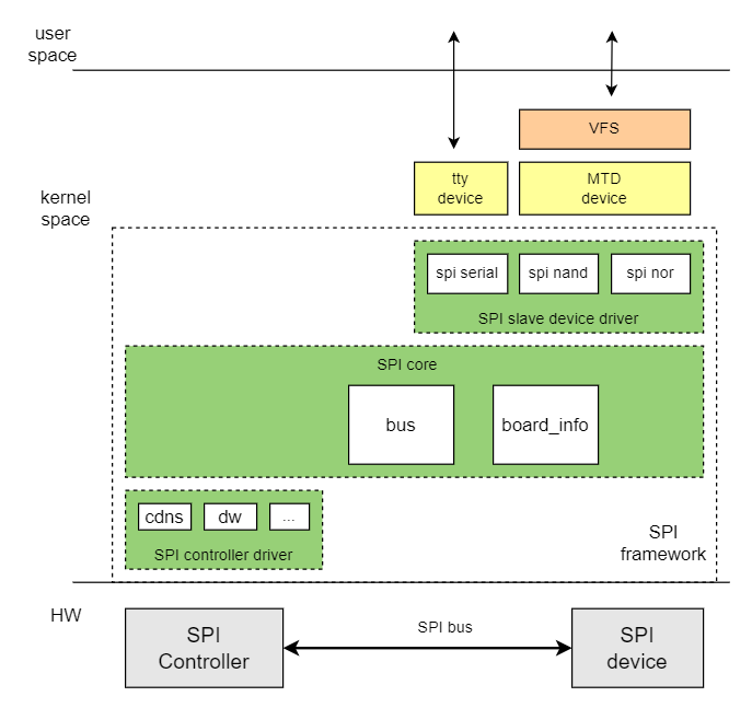
The Linux SPI driver framework is divided into three parts: SPI core, SPI controller driver, and SPI device driver. SPI core mainly performs the following functions:
- Registers SPI buses and spi_master classes.
- Adds and removes SPI controllers.
- Adds and removes SPI devices.
- Registers and unregisters SPI device drivers.
SPI controller driver:
- SPI controller driver, which operates the SPI Master controller
SPI device driver
- SPI Device driver
Source Code Structure Introduction
The controller driver code is located in the drivers/spi directory:
|-- spi-k1x-qspi.c #K1 QSPI driver
Key Features
| Feature | Description |
|---|---|
| Communication Protocol | Supports SSP/SPI/MicroWire/PSP protocols |
| Communication Frequency | Maximum frequency support is 102MHz, minimum frequency support is 13.25MHz |
| Communication Multiplier | x1/x2/x4 |
| Supported Peripherals | Supports spi-nor and spi-nand |
Performance Parameters
Communication Frequency
The current QSPI controller supports up to 102MHz. The list of supported communication frequencies is as follows:
| Maximum Frequency (MHz)) | Divisor (x) | Actual Frequency |
|---|---|---|
| 409 | 4,5,6,7,8 | 409/x |
| 307 | 2,3,4,5,6,7,8 | 307/x |
| 245 | 3,4,5,6,7,8 | 245/x |
| 223 | 3,4,5,6,7,8 | 223/x |
| 106 | 2,3,4,5,6,7,8 | 106/x |
| 495 | 5,6,7,8 | 495/x |
| 189 | 2,3,4,5,6,7,8 | 189/x |
Communication Multiplier
QSPI supports communication multipliers of x1/x2/x4.
Testing Method: Verify the SCK frequency using an oscilloscope or logic analyzer to confirm the communication multiplier.
Configuration
It mainly includes driver enablement configuration and dts configuration.
CONFIG Configuration
- CONFIG_SPI: Provides support for the SPI bus protocol, with a default value of
Y
Device Drivers
        SPI support (SPI [=y])
- CONFIG_SPI_MEM: Provides support for simplified operations on SPI interface memory devices, with a default value of
Y
Device Drivers
        SPI support (SPI [=y])
                SPI memory extension (SPI_MEM [=y])
- CONFIG_SPI_K1X_QSPI: Provides support for the K1 QSPI controller driver, with a default value of
Y
Device Drivers
        SPI support (SPI [=y])
                K1X QuadSPI Controller (SPI_K1X_QSPI [=y])
DTS Configuration
pinctrl
Check the schematic of the solution to find the pin group used by QSPI. You can refer to the pin configuration definition section in PINCTRL to determine the pin group used by QSPI.
Assuming QSPI can directly use the pinctrl_qspi group defined in k1-x_pinctrl.dtsi.
SPI Device Configuration
You need to confirm the SPI device type, the communication frequency, and the multiplier for QSPI and SPI devices.
Device Type
Confirm the type of SPI device connected to QSPI, whether it is SPI-NOR or SPI-NAND.
Communication Frequency
The maximum communication rate supported by the QSPI controller and SPI device. The list of communication frequencies supported by the current QSPI controller can be found in the Communication Frequency section under Performance Parameters in this document.
Communication Multiplier
QSPI supports communication multipliers of x1/x2/x4.
SPI Device DTS
Taking SPI NOR as an example, using the maximum communication frequency of 26.5MHz, both sending and receiving use x4 communication.
The default maximum communication frequency of the QSPI controller is 26.5MHz. If the maximum communication frequency of the QSPI controller is 26.5MHz, the k1x,qspi-freq configuration item can be omitted in the solution DTS.
&qspi {
    k1x,qspi-freq = <26500000>;

    flash@0 {
                compatible = "jedec,spi-nor";
                reg = <0>;
                spi-max-frequency = <26500000>;
                spi-tx-bus-width = <4>;
                spi-rx-bus-width = <4>;
                m25p,fast-read;
                broken-flash-reset;
                status = "okay";
        };
};
DTS Example
SPI-NOR
Combining the above information, QSPI is connected to SPI-NOR flash with a maximum communication frequency of 26.5MHz and using x4 communication.
Example DTS configuration:
&qspi {
        pinctrl-names = "default";
        pinctrl-0 = <&pinctrl_qspi>;
        status = "okay";
        k1x,qspi-freq = <26500000>;

        flash@0 {
                compatible = "jedec,spi-nor";
                reg = <0>;
                spi-max-frequency = <26500000>;
                spi-tx-bus-width = <4>;
                spi-rx-bus-width = <4>;
                m25p,fast-read;
                broken-flash-reset;
                status = "okay";
        };
};
SPI-NAND
QSPI is connected to SPI-NAND flash with a maximum communication frequency of 26.5MHz and using x4 communication.
The solution DTS configuration can refer to SPI-NOR, only the flash device node needs to be modified.
&qspi {
        pinctrl-names = "default";
        pinctrl-0 = <&pinctrl_qspi>;
        status = "okay";
        k1x,qspi-freq = <26500000>;

        spinand: spinand@0 {
                compatible = "spi-nand";
                spi-max-frequency = <26500000>;
                reg = <0>;
                spi-tx-bus-width = <4>;
                spi-rx-bus-width = <4>;
                status = "okay";
        };
};
Interface
API
Device driver registration and unregistration.
int __spi_register_driver(struct module *owner, struct spi_driver *sdrv);
void spi_unregister_driver(struct spi_driver *sdrv);
Data transfer APIs
- Initialize
spi_message
void spi_message_init(struct spi_message *m);
- Add
spi_transferto the transfer list ofspi_message
void spi_message_add_tail(struct spi_transfer *t, struct spi_message *m);
- Write data
int spi_write(struct spi_device *spi, const void *buf, size_t len);
- Read data
int spi_read(struct spi_device *spi, void *buf, size_t len);
- Synchronous transfer of spi_message
int spi_sync(struct spi_device *spi, struct spi_message *message);
Debugging
sysfs
View system SPI bus devices and driver information /sys/bus/spi
|-- devices                 //Devices on the SPI bus
|-- drivers                 //Drivers registered on the SPI bus
|-- drivers_autoprobe
|-- drivers_probe
`-- uevent
debugfs
Used to view information about SPI devices in the system
/sys/kernel/debug/spi-nor/spi4.0
|-- capabilities
`-- params
# cat capabilities
Supported read modes by the flash
 1S-1S-1S
  opcode        0x03
  mode cycles   0
  dummy cycles  0
 1S-1S-1S (fast read)
  opcode        0x0b
  mode cycles   0
  dummy cycles  8

Supported page program modes by the flash
 1S-1S-1S
  opcode        0x02
# cat params
name            w25q32
id              ef 40 16 00 00 00
size            4.00 MiB
write size      1
page size       256
address nbytes  3
flags           BROKEN_RESET | HAS_16BIT_SR

opcodes
 read           0x0b
  dummy cycles  8
 erase          0x20
 program        0x02
 8D extension   none

protocols
 read           1S-1S-1S
 write          1S-1S-1S
 register       1S-1S-1S

erase commands
 20 (4.00 KiB) [0]
 d8 (64.0 KiB) [1]
 c7 (4.00 MiB)

sector map
 region (in hex)   | erase mask | flags
 ------------------+------------+----------
 00000000-003fffff |     [01  ] |
Testing
SPI-NAND/NOR Read/Write Speed Test
Enable CONFIG_MTD_TEST
Device Drivers
         Memory Technology Device (MTD) support (MTD [=y])
                MTD tests support (DANGEROUS) (MTD_TESTS [=m])
Testing command:
insmod mtd_speedtest.ko dev=0 # Specifies the MTD device index for SPI-NAND/NOR