SpacemiT Display Panel Driver Use Cases
This document describes the use cases and debugging methods for MIPI and HDMI screen drivers on the SpacemiT K1 platform in both U-Boot and the Linux Kernel.
Module Introduction
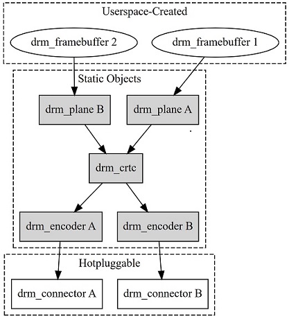
The Display module on the SpacemiT platform is implemented based on the DRM (Direct Rendering Manager) framework.
DRM is a mainstream display framework in the Linux system, well-suited to modern display hardware features.
In the Linux kernel, DRM acts as a subsystem for managing display devices, mainly responsible for the following tasks:
- Display hardware abstraction and management: Unified management of different types of display hardware.
- Graphics memory management: Allocation and control of video memory usage.
- Display output control: Coordination of composition and output of display content.
- Multi-display interface support: Compatibility with multiple interfaces such as HDMI, DSI, eDP.
Uboot Screen Debugging
Source Code Structure Introduction
The source code structure of the SpacemiT platform Uboot display driver is as follows:
uboot-2022.10/drivers/video$ tree spacemit
spacemit
├── dsi
│   ├── drv
│   │   ├── spacemit_dphy.c                                  // MIPI DSI DPHY driver
│   │   ├── spacemit_dphy.h
│   │   ├── spacemit_dsi_common.c
│   │   ├── spacemit_dsi_drv.c                               // MIPI DSI driver
│   │   ├── spacemit_dsi_drv.h
│   │   └── spacemit_dsi_hw.h
│   ├── include
│   │   ├── spacemit_dsi_common.h
│   │   └── spacemit_video_tx.h
│   ├── Makefile
│   └── video
│       ├── lcd                                               // panel configurations
│       │   ├── lcd_ft8201sinx101.c
│       │   ├── lcd_gx09inx101.c
│       │   ├── lcd_icnl9911c.c
│       │   ├── lcd_icnl9951r.c
│       │   ├── lcd_jd9365dah3.c
│       │   └── lcd_lt8911ext_edp_1080p.c
│       ├── spacemit_mipi_port.c
│       └── spacemit_video_tx.c
├── Kconfig
├── Makefile
├── spacemit_dpu.c                                            // DPU driver
├── spacemit_dpu.h
├── spacemit_edp.c                                            // eDP panel driver
├── spacemit_hdmi.c                                           // HDMI driver
├── spacemit_hdmi.h
├── spacemit_mipi.c                                           // MIPI driver
└── spacemit_mipi.h
Configuration Introduction
CONFIG Settings
-
Run
make uboot-menuconfig -
Navigate to Device Drivers -> Graphics support, and enable the following configurations (these are enabled by default).
Device Drivers  --->
  Graphics support  --->
     <*> Enable SPACEMIT Video Suppor
     <*>    HDMI port
     <*>    MIPI Port
     <*>        EDP Port
HDMI DTS Configuration
Configure the HDMI-related device tree as follows.
Set the status = "okay" for the dpu and hdmi nodes.
//uboot-2022.10/arch/riscv/dts/k1-x_deb1.dts
&dpu {
        status = "okay";
};

&hdmi {
        pinctrl-names = "default";
        pinctrl-0 = <&pinctrl_hdmi_0>;          //pinctrl
        status = "okay";
};
MIPI DTS Configuration
MIPI DSI
-
GPIO Definition
Taking the k1-x_deb1 scheme as an example for GPIO configuration of the MIPI DSI panel:- GPIO81: Configured as the panel reset pin.
- GPIO82 and GPIO83: Configured as panel power control pins.
// uboot-2022.10/arch/riscv/dts/k1-x_deb1.dts
&dpu {
        status = "okay";
};

&mipi_dsi {
        status = "okay";
};

&panel {
        dcp-gpios = <&gpio 82 0>;          // Configure panel power control GPIO
        dcn-gpios = <&gpio 83 0>;          // Configure panel power control GPIO
        backlight = <&backlight>;          // Configure backlight PWM
        reset-gpios = <&gpio 81 0>;        // Configure panel reset GPIO
        status = "okay";
}; -
DSI Power Configuration
MIPI DSI requires 1.2V power supply support.
In the k1-x_deb1 scheme:- Use PMIC's ldo_5 as the MIPI DSI 1.2V power supply.
- No additional configuration is needed in the actual scheme, as this power supply is enabled by default.
//uboot-2022.10/arch/riscv/dts/k1-x_deb1.dts
&ldo_27 {
    regulator-init-microvolt = <1200000>;
    regulator-boot-on;
    regulator-state-mem {
                    regulator-off-in-suspend;
    };
};
//uboot-2022.10/arch/riscv/dts/k1-x_spm8821.dtsi
/* dldo */
ldo_27: LDO_REG5 {
regulator-name = "ldo5";
regulator-min-microvolt = <500000>;
regulator-max-microvolt = <3400000>;
regulator-state-mem {
regulator-off-in-suspend;
};
}; -
PWM Backlight Configuration
Backlight is controlled via PWM.&pwm14 {
pinctrl-names = "default";
pinctrl-0 = <&pinctrl_pwm14_1>;
status = "okay";
};
&backlight {
pwms = <&pwm14 0 2000>;
default-brightness-level = <6>;
status = "okay";
};
Display Timing Configuration
In the U-Boot stage, the system uses the following default clock configurations:
- pix-clock: 88,000,000 Hz
- bit-clock: 614,400,000 Hz
Therefore, no additional configuration is required.
//uboot-2022.10/drivers/video/spacemit/spacemit_mipi.c
        pix_clk = dev_read_u32_default(dev, "pix-clk", 88000000);
        ret = clk_set_rate(&priv->pxclk, pix_clk);

        if (ret < 0) {
                pr_err("clk_set_rate mipi dsi pxclk failed: %d\n", ret);
                return ret;
        }

        bit_clk = dev_read_u32_default(dev, "bit-clk", 614400000);
        ret = clk_set_rate(&priv->bitclk, bit_clk);
        if (ret < 0) {
                pr_err("clk_set_rate mipi dsi bitclk failed: %d\n", ret);
                return ret;
        }
The MIPI DSI panel related driver files, which have completed functional debugging, are located in the lcd directory:
uboot-2022.10/drivers/video/spacemit/dsi/video$ tree lcd
lcd
├── lcd_ft8201sinx101.c
├── lcd_gx09inx101.c
├── lcd_icnl9911c.c
├── lcd_icnl9951r.c
├── lcd_jd9365dah3.c
└── lcd_lt8911ext_edp_1080p.c
Example Reference for Adding a New MIPI Panel
The following example uses lcd_gx09inx101 to demonstrate how to add support for a MIPI DSI panel on the SpacemiT platform.
-
Create a New Driver File
Create a new file namedlcd_gx09inx101.cunder the pathuboot-2022.10/drivers/video/spacemit/dsi/video/lcd/with the following content:/ SPDX-License-Identifier: GPL-2.0
/*
* Copyright (C) 2023 SpacemiT Co., Ltd.
*
*/
#include <linux/kernel.h>
#include "../../include/spacemit_dsi_common.h"
#include "../../include/spacemit_video_tx.h"
#include <linux/delay.h>
#define UNLOCK_DELAY 0
// Display Parameter Configuration
struct spacemit_mode_modeinfo gx09inx101_spacemit_modelist[] = {
{
.name = "1200x1920-60",
.refresh = 60, // fps
.xres = 1200, // width (pixels)
.yres = 1920, // height (pixels)
.real_xres = 1200,
.real_yres = 1920,
.left_margin = 40, // horizontal back porch (hbp)
.right_margin = 80, // horizontal front porch (hfp)
.hsync_len = 10, // horizontal sync (hsync)
.upper_margin = 16, // vertical back porch (vbp)
.lower_margin = 20, // vertical front porch (vfp)
.vsync_len = 4, // vertical sync (vsync)
.hsync_invert = 0,
.vsync_invert = 0,
.invert_pixclock = 0,
.pixclock_freq = 156*1000, // pixel clock frequency
.pix_fmt_out = OUTFMT_RGB888,
.width = 142, // physical screen width (mm)
.height = 228, // physical screen height (mm)
},
};
// MIPI DSI interface parameters
struct spacemit_mipi_info gx09inx101_mipi_info = {
.height = 1920, // Screen height configured in MIPI DSI DPHY
.width = 1200, // Screen width configured in MIPI DSI DPHY
.hfp = 80, // Horizontal Front Porch
.hbp = 40, // Horizontal Back Porch
.hsync = 10, // Horizontal Sync pulse width
.vfp = 20, // Vertical Front Porch
.vbp = 16, // Vertical Back Porch
.vsync = 4, // Vertical Sync pulse width
.fps = 60, // Frames per second (refresh rate)
.work_mode = SPACEMIT_DSI_MODE_VIDEO, /* Work mode: command_mode or video_mode */
.rgb_mode = DSI_INPUT_DATA_RGB_MODE_888, // MIPI DSI data format: RGB888 mode
.lane_number = 4, // Number of MIPI DSI lanes
.phy_bit_clock = 614400000, // MIPI DSI DPHY bit clock frequency (Hz)
.phy_esc_clock = 51200000, // MIPI DSI DPHY escape clock frequency (Hz)
.split_enable = 0, // Enable split mode (0 = disabled)
.eotp_enable = 0, // Enable End of Transmission Packet (EoTp) (0 = disabled)
.burst_mode = DSI_BURST_MODE_BURST, // Burst mode configuration
};
static struct spacemit_dsi_cmd_desc gx09inx101_set_id_cmds[] = {
{SPACEMIT_DSI_SET_MAX_PKT_SIZE, SPACEMIT_DSI_LP_MODE, UNLOCK_DELAY, 1, {0x01}},
};
static struct spacemit_dsi_cmd_desc gx09inx101_read_id_cmds[] = {
{SPACEMIT_DSI_GENERIC_READ1, SPACEMIT_DSI_LP_MODE, UNLOCK_DELAY, 1, {0xfb}},
};
static struct spacemit_dsi_cmd_desc gx09inx101_set_power_cmds[] = {
{SPACEMIT_DSI_SET_MAX_PKT_SIZE, SPACEMIT_DSI_HS_MODE, UNLOCK_DELAY, 1, {0x1}},
};
static struct spacemit_dsi_cmd_desc gx09inx101_read_power_cmds[] = {
{SPACEMIT_DSI_GENERIC_READ1, SPACEMIT_DSI_HS_MODE, UNLOCK_DELAY, 1, {0xA}},
};
static struct spacemit_dsi_cmd_desc gx09inx101_init_cmds[] = {
        //8279 + INX10.1
        {SPACEMIT_DSI_DCS_LWRITE, SPACEMIT_DSI_LP_MODE, 0,   2, {0xB0,0x01}},
        {SPACEMIT_DSI_DCS_LWRITE, SPACEMIT_DSI_LP_MODE, 0,   2, {0xC3,0x4F}},
        {SPACEMIT_DSI_DCS_LWRITE, SPACEMIT_DSI_LP_MODE, 0,   2, {0xC4,0x40}},
        {SPACEMIT_DSI_DCS_LWRITE, SPACEMIT_DSI_LP_MODE, 0,   2, {0xC5,0x40}},
        {SPACEMIT_DSI_DCS_LWRITE, SPACEMIT_DSI_LP_MODE, 0,   2, {0xC6,0x40}},
        {SPACEMIT_DSI_DCS_LWRITE, SPACEMIT_DSI_LP_MODE, 0,   2, {0xC7,0x40}},
        {SPACEMIT_DSI_DCS_LWRITE, SPACEMIT_DSI_LP_MODE, 0,   2, {0xC8,0x4D}},
        {SPACEMIT_DSI_DCS_LWRITE, SPACEMIT_DSI_LP_MODE, 0,   2, {0xC9,0x52}},
        {SPACEMIT_DSI_DCS_LWRITE, SPACEMIT_DSI_LP_MODE, 0,   2, {0xCA,0x51}},
        {SPACEMIT_DSI_DCS_LWRITE, SPACEMIT_DSI_LP_MODE, 0,   2, {0xCD,0x5D}},
        {SPACEMIT_DSI_DCS_LWRITE, SPACEMIT_DSI_LP_MODE, 0,   2, {0xCE,0x5B}},
        {SPACEMIT_DSI_DCS_LWRITE, SPACEMIT_DSI_LP_MODE, 0,   2, {0xCF,0x4B}},
        {SPACEMIT_DSI_DCS_LWRITE, SPACEMIT_DSI_LP_MODE, 0,   2, {0xD0,0x49}},

                ·······

        {SPACEMIT_DSI_DCS_LWRITE, SPACEMIT_DSI_LP_MODE, 0,   2, {0xDA,0x19}},
        {SPACEMIT_DSI_DCS_LWRITE, SPACEMIT_DSI_LP_MODE, 0,   2, {0xDB,0x17}},
        {SPACEMIT_DSI_DCS_LWRITE, SPACEMIT_DSI_LP_MODE, 0,   2, {0xDC,0x17}},
        {SPACEMIT_DSI_DCS_LWRITE, SPACEMIT_DSI_LP_MODE, 0,   2, {0xDD,0x18}},
        {SPACEMIT_DSI_DCS_LWRITE, SPACEMIT_DSI_LP_MODE, 0,   2, {0xDE,0x1A}},
        {SPACEMIT_DSI_DCS_LWRITE, SPACEMIT_DSI_LP_MODE, 0,   2, {0xDF,0x1E}},
        {SPACEMIT_DSI_DCS_LWRITE, SPACEMIT_DSI_LP_MODE, 0,   2, {0xE0,0x20}},
        {SPACEMIT_DSI_DCS_LWRITE, SPACEMIT_DSI_LP_MODE, 0,   2, {0xE1,0x23}},
        {SPACEMIT_DSI_DCS_LWRITE, SPACEMIT_DSI_LP_MODE, 0,   2, {0xE2,0x07}},
        {SPACEMIT_DSI_DCS_LWRITE, SPACEMIT_DSI_LP_MODE, 200, 2, {0x11, 0x00}},
        {SPACEMIT_DSI_DCS_LWRITE, SPACEMIT_DSI_LP_MODE,  50, 2, {0x29, 0x00}},
};
static struct spacemit_dsi_cmd_desc gx09inx101_sleep_out_cmds[] = {
{SPACEMIT_DSI_DCS_SWRITE,SPACEMIT_DSI_LP_MODE,200,1,{0x11}},
{SPACEMIT_DSI_DCS_SWRITE,SPACEMIT_DSI_LP_MODE,50,1,{0x29}},
};
static struct spacemit_dsi_cmd_desc gx09inx101_sleep_in_cmds[] = {
{SPACEMIT_DSI_DCS_SWRITE,SPACEMIT_DSI_LP_MODE,50,1,{0x28}},
{SPACEMIT_DSI_DCS_SWRITE,SPACEMIT_DSI_LP_MODE,200,1,{0x10}},
};
struct lcd_mipi_panel_info lcd_gx09inx101 = {
.lcd_name = "gx09inx101",
.lcd_id = 0x8279,
.panel_id0 = 0x1,
.power_value = 0x14,
.panel_type = LCD_MIPI,
.width_mm = 142,
.height_mm = 228,
.dft_pwm_bl = 128,
.set_id_cmds_num = ARRAY_SIZE(gx09inx101_set_id_cmds),
.read_id_cmds_num = ARRAY_SIZE(gx09inx101_read_id_cmds),
.init_cmds_num = ARRAY_SIZE(gx09inx101_init_cmds),
.set_power_cmds_num = ARRAY_SIZE(gx09inx101_set_power_cmds),
.read_power_cmds_num = ARRAY_SIZE(gx09inx101_read_power_cmds),
.sleep_out_cmds_num = ARRAY_SIZE(gx09inx101_sleep_out_cmds),
.sleep_in_cmds_num = ARRAY_SIZE(gx09inx101_sleep_in_cmds),
//.drm_modeinfo = gx09inx101_modelist,
.spacemit_modeinfo = gx09inx101_spacemit_modelist,
.mipi_info = &gx09inx101_mipi_info,
.set_id_cmds = gx09inx101_set_id_cmds,
.read_id_cmds = gx09inx101_read_id_cmds,
.set_power_cmds = gx09inx101_set_power_cmds,
.read_power_cmds = gx09inx101_read_power_cmds,
.init_cmds = gx09inx101_init_cmds,
.sleep_out_cmds = gx09inx101_sleep_out_cmds,
.sleep_in_cmds = gx09inx101_sleep_in_cmds,
.bitclk_sel = 3,
.bitclk_div = 1,
.pxclk_sel = 2,
.pxclk_div = 6,
};
int lcd_gx09inx101_init(void)
{
int ret;
ret = lcd_mipi_register_panel(&lcd_gx09inx101);
return ret;
}
Configure the following items according to the screen specifications.
-
Initialization commands (initial-cmd):
static struct spacemit_dsi_cmd_desc gx09inx101_init_cmds[] = {
//8279 + INX10.1
{SPACEMIT_DSI_DCS_LWRITE, SPACEMIT_DSI_LP_MODE, 0, 2, {0xB0,0x01}},
{SPACEMIT_DSI_DCS_LWRITE, SPACEMIT_DSI_LP_MODE, 0, 2, {0xC3,0x4F}},
{SPACEMIT_DSI_DCS_LWRITE, SPACEMIT_DSI_LP_MODE, 0, 2, {0xC4,0x40}},
{SPACEMIT_DSI_DCS_LWRITE, SPACEMIT_DSI_LP_MODE, 0, 2, {0xC5,0x40}},
{SPACEMIT_DSI_DCS_LWRITE, SPACEMIT_DSI_LP_MODE, 0, 2, {0xC6,0x40}},
{SPACEMIT_DSI_DCS_LWRITE, SPACEMIT_DSI_LP_MODE, 0, 2, {0xC7,0x40}},
{SPACEMIT_DSI_DCS_LWRITE, SPACEMIT_DSI_LP_MODE, 0, 2, {0xC8,0x4D}},
{SPACEMIT_DSI_DCS_LWRITE, SPACEMIT_DSI_LP_MODE, 0, 2, {0xC9,0x52}},
{SPACEMIT_DSI_DCS_LWRITE, SPACEMIT_DSI_LP_MODE, 0, 2, {0xCA,0x51}},
{SPACEMIT_DSI_DCS_LWRITE, SPACEMIT_DSI_LP_MODE, 0, 2, {0xCD,0x5D}},
{SPACEMIT_DSI_DCS_LWRITE, SPACEMIT_DSI_LP_MODE, 0, 2, {0xCE,0x5B}},
{SPACEMIT_DSI_DCS_LWRITE, SPACEMIT_DSI_LP_MODE, 0, 2, {0xCF,0x4B}},
{SPACEMIT_DSI_DCS_LWRITE, SPACEMIT_DSI_LP_MODE, 0, 2, {0xD0,0x49}},
·······
{SPACEMIT_DSI_DCS_LWRITE, SPACEMIT_DSI_LP_MODE, 0, 2, {0xDA,0x19}},
{SPACEMIT_DSI_DCS_LWRITE, SPACEMIT_DSI_LP_MODE, 0, 2, {0xDB,0x17}},
{SPACEMIT_DSI_DCS_LWRITE, SPACEMIT_DSI_LP_MODE, 0, 2, {0xDC,0x17}},
{SPACEMIT_DSI_DCS_LWRITE, SPACEMIT_DSI_LP_MODE, 0, 2, {0xDD,0x18}},
{SPACEMIT_DSI_DCS_LWRITE, SPACEMIT_DSI_LP_MODE, 0, 2, {0xDE,0x1A}},
{SPACEMIT_DSI_DCS_LWRITE, SPACEMIT_DSI_LP_MODE, 0, 2, {0xDF,0x1E}},
{SPACEMIT_DSI_DCS_LWRITE, SPACEMIT_DSI_LP_MODE, 0, 2, {0xE0,0x20}},
{SPACEMIT_DSI_DCS_LWRITE, SPACEMIT_DSI_LP_MODE, 0, 2, {0xE1,0x23}},
{SPACEMIT_DSI_DCS_LWRITE, SPACEMIT_DSI_LP_MODE, 0, 2, {0xE2,0x07}},
{SPACEMIT_DSI_DCS_LWRITE, SPACEMIT_DSI_LP_MODE, 200, 2, {0x11, 0x00}},
{SPACEMIT_DSI_DCS_LWRITE, SPACEMIT_DSI_LP_MODE, 50, 2, {0x29, 0x00}},
}; -
Panel ID Recognition (Confirm Screen Model) Verify that the connected screen model is compatible with the driver. Configure read_id to read the panel_id.
For example, lcd_gx09inx101 reads register0xfb.//uboot-2022.10/drivers/video/spacemit/dsi/video/lcd/lcd_gx09inx101.c
static struct spacemit_dsi_cmd_desc gx09inx101_read_id_cmds[] = {
{SPACEMIT_DSI_GENERIC_READ1, SPACEMIT_DSI_LP_MODE, UNLOCK_DELAY, 1, {0xfb}},
};Compare the returned value with the expected one; if they do not match, report an error.
For example, the value read from register0xfbis expected to be0x1.//uboot-2022.10/drivers/video/spacemit/dsi/video/lcd/lcd_gx09inx101.c
struct lcd_mipi_panel_info lcd_gx09inx101 = {
.lcd_name = "gx09inx101",
.panel_id0 = 0x1, -
ESD (Electrostatic Discharge) Protection Check
Continuously monitor the screen's operating status to prevent damage caused by static electricity.
In thelcd_gx09inx101configuration, the ESD check reads register0xA.//uboot-2022.10/drivers/video/spacemit/dsi/video/lcd/lcd_gx09inx101.c
static struct spacemit_dsi_cmd_desc gx09inx101_read_power_cmds[] = {
{SPACEMIT_DSI_GENERIC_READ1, SPACEMIT_DSI_HS_MODE, UNLOCK_DELAY, 1, {0xA}},
};The driver compares the read result with a preset
power_value.
If they differ, it indicates a possible ESD fault on the screen.
In the example, register0xAis expected to return a value matchingpower_value://uboot-2022.10/drivers/video/spacemit/dsi/video/lcd/lcd_gx09inx101.c
struct lcd_mipi_panel_info lcd_gx09inx101 = {
.power_value = 0x10,
-
Modify Makefile Add the new panel in
obj-y//uboot-2022.10/drivers/video/spacemit/dsi/Makefile
# SPDX-License-Identifier: GPL-2.0
obj-y += video/spacemit_video_tx.o \
video/spacemit_mipi_port.o \
drv/spacemit_dphy.o \
drv/spacemit_dsi_common.o \
drv/spacemit_dsi_drv.o
obj-y += video/lcd/lcd_icnl9911c.o
obj-y += video/lcd/lcd_icnl9951r.o
obj-y += video/lcd/lcd_jd9365dah3.o
obj-y += video/lcd/lcd_gx09inx101.o
obj-y += video/lcd/lcd_lt8911ext_edp_1080p.o -
Modify the header file
spacemit_dsi_common.h//uboot-2022.10/drivers/video/spacemit/dsi/include/spacemit_dsi_common.h
int lcd_icnl9911c_init(void);
int lcd_icnl9951r_init(void);
int lcd_gx09inx101_init(void); // Add declarations for the corresponding functions implemented in lcd_gx09inx101.c
int lcd_jd9365dah3_init(void);
int lcd_lt8911ext_edp_1080p_init(void); -
Modify Port Recognition Logic in
spacemit_mipi_port.c
Add new panel in the panel matching logic//uboot-2022.10/drivers/video/spacemit/dsi/video/spacemit_mipi_port.c
if (strcmp("lt8911ext_edp_1080p", priv->panel_name) == 0) {
tx_device_client.panel_type = LCD_EDP;
tx_device.panel_type = tx_device_client.panel_type;
lcd_lt8911ext_edp_1080p_init();
} else if(strcmp("icnl9951r", priv->panel_name) == 0) {
tx_device_client.panel_type = LCD_MIPI;
tx_device.panel_type = tx_device_client.panel_type;
lcd_icnl9951r_init();
} else if(strcmp("jd9365dah3", priv->panel_name) == 0) {
tx_device_client.panel_type = LCD_MIPI;
tx_device.panel_type = tx_device_client.panel_type;
lcd_jd9365dah3_init();
} else {
// lcd_icnl9911c_init();
lcd_gx09inx101_init(); // Add gx09inx101 panel recognition, refer to the above three for adding other new panels
}
After this modification, the gx09inx101 panel can be correctly recognized and driven during U-Boot initialization.
U-Boot Startup Related Logs
Below are the key logs of MIPI DSI Panel initialization during the U-Boot startup process:
[   0.842] Found device 'mipi@d421a800', disp_uc_priv=000000007deb1aa0
            /* Read ID, corresponds to the configuration of struct lcd_mipi_panel_info lcd_gx09inx101.id0 in lcd_gx09inx101.c */
[   1.001] read panel id OK: read value = 0x1, 0x0, 0x0
[   1.003] Panel is gx09inx101
[   1.260] fb=7f700000, size=1200x1920
Kernel Screen Debugging
For the functions and usage of the SpacemiT platform Display module, refer to: SpacemiT Platform Display Module Introduction
HDMI Configuration
The following example is based on the k1-x_deb1 solution and demonstrates the device tree configuration for HDMI:
// linux-6.6\arch\riscv\boot\dts\spacemit\k1-x_deb1.dts
&dpu_online2_hdmi {
        memory-region = <&dpu_resv>;             // Configure HDMI DPU reserved memory
        status = "okay";
};

&hdmi{
        pinctrl-names = "default";
        pinctrl-0 = <&pinctrl_hdmi_0>;
        status = "okay";
};
MIPI DSI Panel Configuration Example
During the kernel phase, the configuration steps for a MIPI screen are as follows:
-
Configure power supply and GPIO
-
Create a new MIPI screen dtsi file
-
Configure timing and commands according to vendor data
Refer to the MIPI screen parameters provided by the screen vendor and the main control chip datasheet. Combine information such as screen timing to configure in the dtsi file:- clock parameters (front and back porch, resolution, and calculated pixel clock and bit clock)
- initialization commands (initial-command)
- ID reading commands (read-id-command)
-
Associate the MIPI Panel with the solution
k1-x_deb1 Solution
The following example shows the DTS configuration for using lcd_gx09inx101_mipi as the display in the k1-x_deb1 solution
//linux-6.6/arch/riscv/boot/dts/spacemit/k1-x_deb1.dts
#include "lcd/lcd_gx09inx101_mipi.dtsi"
#include "k1-x-lcd.dtsi"
#include "k1-x-hdmi.dtsi"

&dpu_online2_dsi {
        memory-region = <&dpu_resv>;
        spacemit-dpu-bitclk = <1000000000>;     // bit clock, calculated based on timing
        spacemit-dpu-escclk = <76800000>;
        dsi_1v2-supply = <&ldo_5>;              // Reference PMIC DLDO1
        vin-supply-names = "dsi_1v2";           // Configure MIPI DSI 1.2v
        status = "okay";
};

&dsi2 {
        status = "okay";

        panel2: panel2@0 {
                status = "okay";
                compatible = "spacemit,mipi-panel2";
                reg = <0>;

                gpios-reset = <81>;             // Configure panel reset GPIO
                gpios-dc = <82 83>;             // Configure panel power control GPIOs
                id = <2>;                      // Configure panel ID
                delay-after-reset = <10>;       // Configure panel reset delay time (unit: ms)
                force-attached = "lcd_gx09inx101_mipi"; // Associate solution with panel
        };
};

&lcds {
        status = "okay";                        // Enable LCDs
};

&pwm14 {                                        // Configure PWM
        pinctrl-names = "default";
        pinctrl-0 = <&pinctrl_pwm14_1>;
        status = "okay";
};

&pwm_bl {                                       // Configure backlight
        pwms = <&pwm14 2000>;
        brightness-levels = <
                0   20  20  20  21  21  21  22  22  22  23  23  23  24  24  24
                25  25  25  26  26  26  27  27  27  28  28  29  29  30  30  31
                32  33  34  35  36  37  38  39  40  41  42  43  44  45  46  47
                48  49  50  51  52  53  54  55  56  57  58  59  60  61  62  63
                64  65  66  67  68  69  70  71  72  73  74  75  76  77  78  79
                80  81  82  83  84  85  86  87  88  89  90  91  92  93  94  95
                96  97  98  99  100 101 102 103 104 105 106 107 108 109 110 111
                112 113 114 115 116 117 118 119 120 121 122 123 124 125 126 127
                128 129 130 131 132 133 134 135 136 137 138 139 140 141 142 143
                144 145 146 147 148 149 150 151 152 153 154 155 156 157 158 159
                160 161 162 163 164 165 166 167 168 169 170 171 172 173 174 175
                176 177 178 179 180 181 182 183 184 185 186 187 188 189 190 191
                192 193 194 195 196 197 198 199 200 201 202 203 204 205 206 207
                208 209 210 211 212 213 214 215 216 217 218 219 220 221 222 223
                224 225 226 227 228 229 230 231 232 233 234 235 236 237 238 239
                240 241 242 243 244 245 246 247 248 249 250 251 252 253 254 255
        >;
        default-brightness-level = <50>;
        status = "okay";
};
DSI Power Supply
DSI requires AVDD1.8 and AVDD1.2 power supplies
-
AVDD1.8_DSI: Supplied by BUCK3_1V8 by default, no additional configuration needed.
-
AVDD1.2_DSI: Supplied by DLDO1, needs to be specified in the dts:
dsi_1v2-supply = <&ldo_5>;              //dldo1
vin-supply-names = "dsi_1v2"
MIPI Screen Power Supply
In this solution, the MIPI interface requires configuration of GPIO and PWM according to the schematic.
-
GPIO
The screen requires reset and power control GPIOs:
dcp-gpios = gpio 82;
dcn-gpios = gpio 83;
reset-gpios = gpio 81;gpios-reset = <81>; // Configure panel reset GPIO
gpios-dc = <82 83>; // Configure panel power control GPIOs -
PWM Use PWM to control backlight, corresponding device tree configuration
&pwm14 {
     pinctrl-names = "default";
     pinctrl-0 = <&pinctrl_pwm14_1>;
     status = "okay";
};
LCD dtsi Configuration
Create a new lcd_gx09inx101_mipi.dtsi file under the linux-6.6/arch/riscv/boot/dts/spacemit/lcd/ directory
// SPDX-License-Identifier: GPL-2.0

/ { lcds: lcds {
        lcd_gx09inx101_mipi: lcd_gx09inx101_mipi {
                dsi-work-mode = <1>;            // Configure MIPI DSI work mode in panel: 1 DSI_MODE_VIDEO_BURST;
                dsi-lane-number = <4>;          // Configure number of MIPI DSI lanes in panel
                dsi-color-format = "rgb888";
                width-mm = <142>;               // Configure screen active area width in panel
                height-mm = <228>;              // Configure screen active area height in panel
                use-dcs-write;                  // Configure whether to use DCS command mode in panel

                /*mipi info*/
                height = <1920>;
                width = <1200>;
                hfp = <80>;
                hbp = <40>;
                hsync = <10>;
                vfp = <20>;
                vbp = <16>;
                vsync = <4>;
                fps = <60>;
                work-mode = <0>;
                rgb-mode = <3>;
                lane-number = <4>;
                phy-bit-clock = <1000000000>;    // Configure MIPI DSI DPHY bit clock
                phy-esc-clock = <76800000>;
                split-enable = <0>;              // Configure MIPI DSI enable in DPHY
                eotp-enable = <0>;               // Configure EOTP enable in MIPI DSI DPHY
                burst-mode = <2>;                // Configure MIPI DSI burst mode in DPHY: 2 DSI_BURST_MODE_BURST;
                esd-check-enable = <0>;          // Enable ESD check in panel configuration
                /* DSI_CMD, DSI_MODE, timeout, len, cmd */
                // initial-command, configured according to screen information
                initial-command = [
                39 01 00 02 B0 01
                39 01 00 02 C3 4F
                39 01 00 02 C4 40
                39 01 00 02 C5 40
                39 01 00 02 C6 40
                39 01 00 02 C7 40
                39 01 00 02 C8 4D

                    ··········

                39 01 00 02 DA 19
                39 01 00 02 DB 17
                39 01 00 02 DC 17
                39 01 00 02 DD 18
                39 01 00 02 DE 1A
                39 01 00 02 DF 1E
                39 01 00 02 E0 20
                39 01 00 02 E1 23
                39 01 00 02 E2 07
                39 01 F0 01 11
                39 01 28 01 29
                ];
                sleep-in-command = [
                        39 01 78 01 28
                        39 01 78 01 10
                ];
                sleep-out-command = [
                        39 01 96 01 11
                        39 01 32 01 29
                ];
                // read-id-command, configured according to screen information
                read-id-command = [
                        37 01 00 01 05
                        14 01 00 05 fb fc fd fe ff
                ];

                display-timings {
                        timing0 {
                                clock-frequency = <153000000>;  // mipi dsi pixclk configuration
                                hactive = <1200>;
                                hfront-porch = <80>;
                                hback-porch = <40>;
                                hsync-len = <10>;
                                vactive = <1920>;
                                vfront-porch = <20>;
                                vback-porch = <16>;
                                vsync-len = <4>;
                                vsync-active = <1>;
                                hsync-active = <1>;
                        };
                };
        };
};};
Timing Calculation
-
Pixel Clock
(hactive + hfp + hbp + hsync) * (vactive + vfp + vbp + vsync) * fps = (1200 + 50 + 40 + 10)* (1920 + 20 + 16 + 4) * 60 = 152880000 Hz
-
Bit Clock
(((hactive + hfp + hbp + hsync) * (vactive + vfp + vbp + vsync) * fps * bpp) / lane bumber) * 1.1 = (((1200 + 50 + 40 + 10)* (1920 + 20 + 16 + 4) * 60 * 24)/ 4) * 1.1 = 1009008000 Hz
From the display-timing results:
- Pixel Clock = 152 880 000 Hz → system uses 153 000 000 Hz
- Bit Clock = 1 009 008 000 Hz → system uses 1 000 000 000 Hz
DTS configuration snippet:
clock-frequency= 153000000 Hzspacemit-dpu-bitclk= 1000000000 Hzphy-bit-clock= 1000000000 Hz
FAQ
1. Configure HDMI Only
Taking the k1-x_deb1 configuration as an example, if you only want to enable HDMI output you can disable the LCD panel and enable HDMI in the driver DTS.
The default configuration is shown below:
//linux-6.6/arch/riscv/boot/dts/spacemit/k1-x_deb1.dts
&dpu_online2_dsi {
        memory-region = <&dpu_resv>;
        spacemit-dpu-bitclk = <1000000000>;
        spacemit-dpu-escclk = <76800000>;
        dsi_1v2-supply = <&ldo_5>;
        vin-supply-names = "dsi_1v2";
        status = "disabled"; // Disable MIPI DSI
};

&dsi2 {
        status = "disabled"; // Disable DSI panel

        panel2: panel2@0 {
                status = "ok";
                compatible = "spacemit,mipi-panel2";
                reg = <0>;

                gpios-reset = <81>;
                gpios-dc = <82 83>;
                id = <2>;
                delay-after-reset = <10>;
                force-attached = "lcd_gx09inx101_mipi";
        };
};

&lcds {
        status = "disabled";  // Disable LCD
};

&dpu_online2_hdmi {
        memory-region = <&dpu_resv>;
        status = "okay"; // Enable HDMI DPU
};

&hdmi{
        pinctrl-names = "default";
        pinctrl-0 = <&pinctrl_hdmi_0>;
        status = "okay";  // Enable HDMI
};
2. Configure HDMI and DSI Simultaneously
If you need to enable both the LCD (MIPI DSI) and HDMI outputs, set the status property of both relevant nodes to "okay" in the DTS.
Example for th ek1-x_deb1 configuration:
//linux-6.6/arch/riscv/boot/dts/spacemit/k1-x_deb1.dts
&dpu_online2_dsi {
        memory-region = <&dpu_resv>;
        spacemit-dpu-bitclk = <1000000000>;
        spacemit-dpu-escclk = <76800000>;
        dsi_1v2-supply = <&ldo_5>;
        vin-supply-names = "dsi_1v2";
        status = "okay"; // Enable MIPI DSI
};

&dsi2 {
        status = "okay";  // Enable DSI panel

        panel2: panel2@0 {
                status = "ok";
                compatible = "spacemit,mipi-panel2";
                reg = <0>;

                gpios-reset = <81>;
                gpios-dc = <82 83>;
                id = <2>;
                delay-after-reset = <10>;
                force-attached = "lcd_gx09inx101_mipi";
        };
};

&lcds {
        status = "okay"; // Enable LCD module
};

&dpu_online2_hdmi {
        memory-region = <&dpu_resv>;
        status = "okay"; // Enable HDMI DPU
};

&hdmi{
        pinctrl-names = "default";
        pinctrl-0 = <&pinctrl_hdmi_0>;
        status = "okay"; // Enable HDMI
};
3. Configure DSI Only
If only the MIPI DSI LCD is required, enable the DSI-related nodes (status = "okay") and disable the HDMI-related nodes (status = "disabled").
Example for the k1-x_deb1 configuration:
//linux-6.6/arch/riscv/boot/dts/spacemit/k1-x_deb1.dts
&dpu_online2_dsi {
        memory-region = <&dpu_resv>;
        spacemit-dpu-bitclk = <1000000000>;
        spacemit-dpu-escclk = <76800000>;
        dsi_1v2-supply = <&ldo_5>;
        vin-supply-names = "dsi_1v2";
        status = "okay"; // Enable MIPI DSI
};

&dsi2 {
        status = "okay"; // Enable DSI panel

        panel2: panel2@0 {
                status = "ok";
                compatible = "spacemit,mipi-panel2";
                reg = <0>;

                gpios-reset = <81>;
                gpios-dc = <82 83>;
                id = <2>;
                delay-after-reset = <10>;
                force-attached = "lcd_gx09inx101_mipi";
        };
};

&lcds {
        status = "okay";  // Enable LCD module
};

&dpu_online2_hdmi {
        memory-region = <&dpu_resv>;
        status = "disabled"; // Disable HDMI DPU
};

&hdmi{
        pinctrl-names = "default";
        pinctrl-0 = <&pinctrl_hdmi_0>;
        status = "disabled"; // Disable HDMI
};
4. Weston Primary Display Configuration
Weston’s launch script is located at:
//buildroot/package/weston/run_weston.sh
Default script
#export EGL_LOG_LEVEL=debug
export MESA_LOADER_DRIVER_OVERRIDE=pvr
export XDG_RUNTIME_DIR=/root
export QT_QPA_PLATFORM_PLUGIN_PATH=/usr/lib/qt/plugins/platforms
export QT_QPA_PLATFORM=wayland
weston --log=/var/log/weston --tty=1 --idle-time=0
When both HDMI and LCD are configured with status = "okay", Weston defaults to using the first DRM display device (i.e., the first card listed under /sys/class/drm).
Check DRM devices
cd /sys/class/drm
ls
card1: bound to LCD by defaultcard2: bound to HDMI by default
Set HDMI as the primary screen
If you want Weston to start on HDMI by default, edit the run_weston.sh script and explicitly specify the DRM device in the launch parameters:
//buildroot/package/weston/run_weston.sh
#export EGL_LOG_LEVEL=debug
export MESA_LOADER_DRIVER_OVERRIDE=pvr
export XDG_RUNTIME_DIR=/root
export QT_QPA_PLATFORM_PLUGIN_PATH=/usr/lib/qt/plugins/platforms
export QT_QPA_PLATFORM=wayland
weston --log=/var/log/weston --tty=1 --drm-device=card2 --idle-time=0
Passing the --drm-device=card2 argument forces Weston to use HDMI as the primary output.
5. Bianbu Primary Screen Configuration
In the Bianbu environment, mutter defaults to treating DSI as the primary display.
To change the primary display to HDMI, you must modify the mutter source code and recompile it.
//mutter/src/backends/meta-monitor.c
meta_monitor_is_laptop_panel (MetaMonitor *monitor)
{
  const MetaOutputInfo *output_info =
    meta_monitor_get_main_output_info (monitor);

  switch (output_info->connector_type)
    {
    case META_CONNECTOR_TYPE_eDP:
    case META_CONNECTOR_TYPE_LVDS:
    case META_CONNECTOR_TYPE_HDMIA: //By default, the configuration uses `META_CONNECTOR_TYPE_DSI`.
      return TRUE;
    default:
      return FALSE;
    }
}
Modification Instructions
- Keep
META_CONNECTOR_TYPE_HDMIAin the branch that returnsTRUE, while removing or commenting outMETA_CONNECTOR_TYPE_DSI.
After modifying the source, recompile and reinstall mutter; the change will take effect immediately.